


NXP Semiconductors
KTFRDM34933EVBUG
FRDM-34933EVB evaluation board
KTFRDM34933EVBUG
All information provided in this document is subject to legal disclaimers.
© NXP B.V. 2017. All rights reserved.
User guide
Rev. 1.0 — 15 March 2017
25 / 39
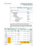
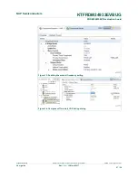
LVHBridge component properties
Primary timer input frequency
Mode
description
Timer device Secondary
timer
Output
control
Motor
control
mode
Values
Min.
Max.
Secondary
timer input
frequency
2nd value
for micro-
step:1.2 MHz
2nd value
for Micro-
step:10 MHz
Full-step
and micro-
step mode
FTM
Enabled
PWM
Full-step
1
1.2 MHz
10 MHz
The same
values as for
primary timer
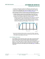
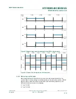
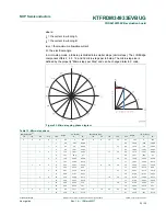
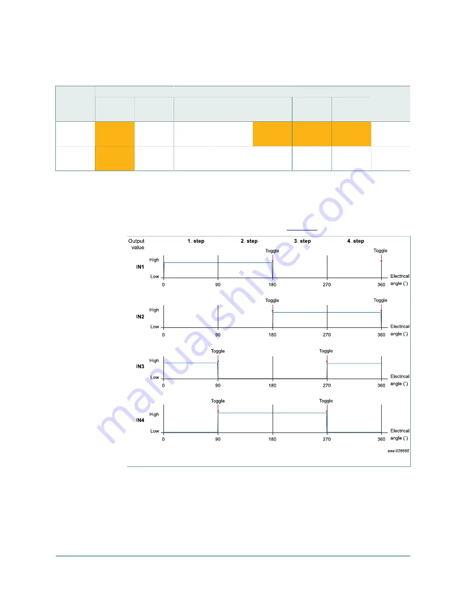
6.5.5.1 Computation of minimum full-stepping speed
The minimum full-stepping speed depends on the timer input frequency only when the
Primary Timer Device is set to FTM (FTM0_CNT, or FTM1_CNT), the Secondary Timer
property is disabled and Output Control is set to PWM. The full-step signal is generated
by a timer while channels toggle on compare (see
Figure 12
).
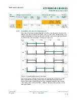
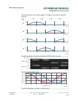
Figure 12. Generating the full-step control signal
The full-step minimum speed is derived from the input frequency of the timer device
(the counter frequency property of the TimerUnit_LDD component being used).
You can find minimum values for speed in the LVHBridge header file (see constant
<component_name>_MIN_FULLSTEP_ SPEED). The formula for calculation of this
value is as follows: