


NXP Semiconductors
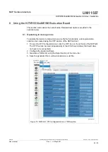
UM11587
KITVR5510xA0EVM Evaluation Kit User Guideline
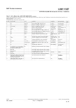
8. Read M_TM_STATUS1[0x25] from the M_TestMode (main) section and
FS_STATES[0x18] register from the safety section in the register map. In this way, the
user can access the OTP mirror registers in debug mode.
Figure 18. M_TM_STATUS1 (0x25)
Figure 19. FS_STATES (0x18)
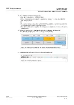
9. On the Script section of the GUI, use the command section to load the debug script
created. Then click Run.
10.When programming the script is finished, remove the jumper from J11 or set SW5 low
to bring the device out of debug and begin operation with the selected configuration.
8.2 Programming/burning OTP in debug mode
To program the OTP, the device must be operated in debug mode and test mode. To
enter debug mode of operation and test mode, follow the steps mentioned in
.An OTP script can be created using the OTP section of the
tool as explained above in
Section 8.1 "Operating in debug mode"
.
Section 8.1 "Operating in debug mode"
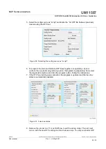
using the Export section of the menu bar (make sure to fill all required fields marked
with a * to enable the file generation Ready).
2. Save the generated OTP file in a known location as a .txt file.
3. To configure the board for test mode and debug mode operation, follow steps 5 to 8.
Verify by reading back the registers to confirm test mode entry.
Note:
to allow access to OTP mirror registers, test mode entry is essential for the
device.
4. Go to the PROG section in the NXPGUI tool. The PROG section is only activated
when the test mode entry is successful.
UM11587
All information provided in this document is subject to legal disclaimers.
© NXP B.V. 2021. All rights reserved.
User manual
Rev. 1 — 3 May 2021
25 / 32