


NXP Semiconductors
UM11183
KITFS85SKTEVM evaluation board
UM11183
All information provided in this document is subject to legal disclaimers.
© NXP B.V. 2019. All rights reserved.
User guide
Rev. 2.0 — 20 February 2019
10 / 50
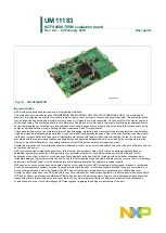
1. V
BAT
Jack connector
2. V
BAT
three position switch
3. V
BAT
Phoenix connector
4. LDO1/LDO2 power supplies
5. VPRE power supply
6. BUCK1/BUCK2 power supply
7. USB connector (for FlexGUI control)
8. Debug connectivity
9. Programming
10. Wake1 switch
11. OTP burning voltage switch
12. VBOOST and BUCK3 power supply
13. DEBUG voltage source
14. Compensation network selection
15. VDDIO selection
16. SPI / RSTb / FS0b connection to MCU
17. RSTb, INTb and FS0b signals
18. VMONx, VDDI2C selection
Figure 12. Evaluation board featured component locations
Table 2. Evaluation board board component descriptions
Number
Description
1
V
BAT
Jack connector
2
V
BAT
three position switch
•
Left position: board supplied by Jack connector
•
Middle position: board not supplied
•
Right position: board supplied by Phoenix connector
3
V
BAT
Phoenix connector
4
LDO1/LDO2 power supply
5
VPRE power supply
6
BUCK1/BUCK2 power supply
7
USB connector (for FlexGUI control)