


Installing the Software and Setting up the Hardware
KT34FS6407-34FS6408UG User’s Guide Rev. 1.0 8/2015
26
Freescale Semiconductor, Inc.
In order to fill a specific need, it is also possible to edit registers with another value and to save it for further use, either as standalone or
inside a batch.
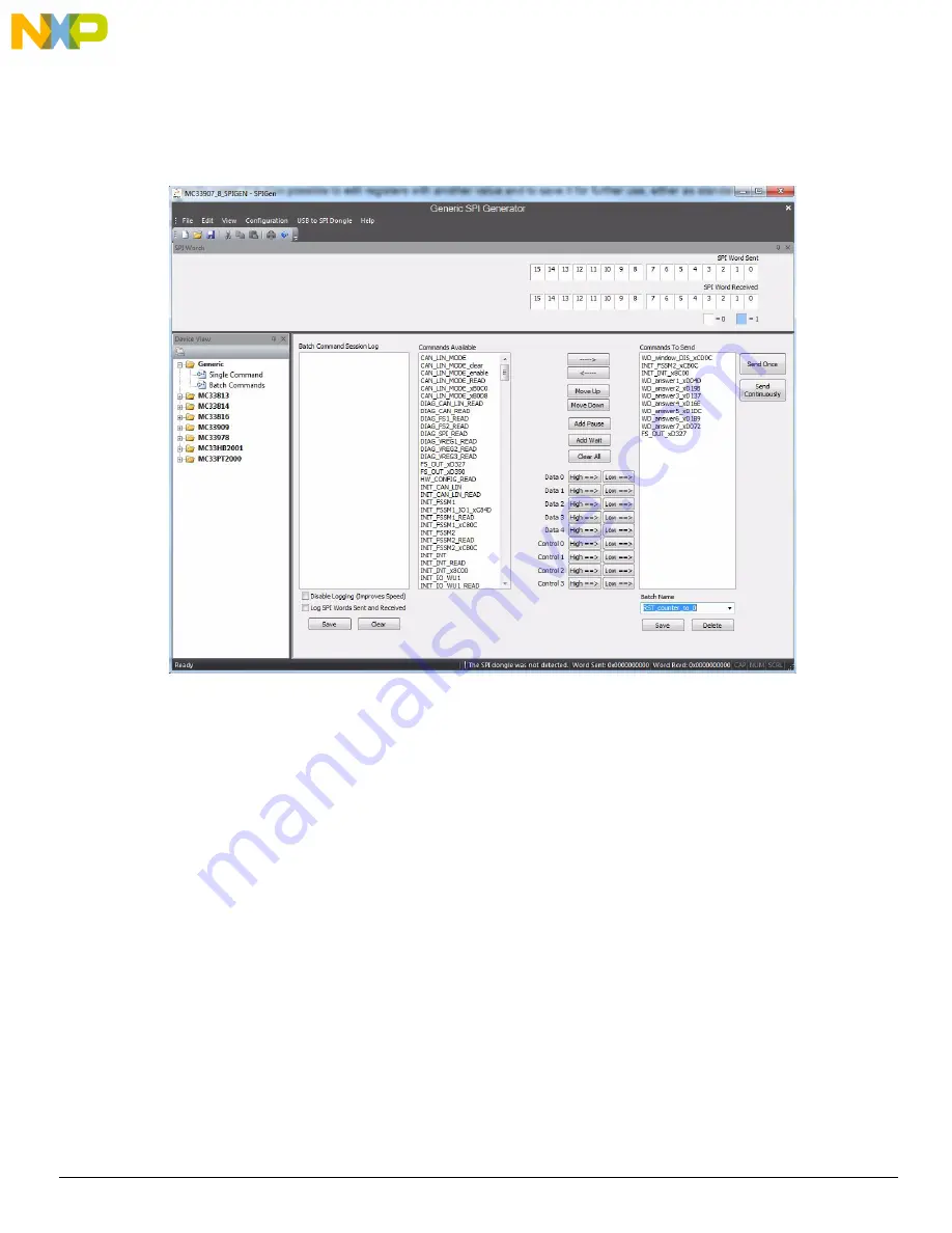
shows a batch called “RST_counter_to_0”, as an example. This batch file automatically installs when the configuration file is
loaded. To select the batch file, click on the Batch Name box at the bottom right side of the screen.
Figure 10. RST_counter_to_0 Batch
At startup or when resuming from LPOFF mode the reset error counter starts at level 1 and FS0B is asserted low. To remove activation of
FS0B, the RST error counter must go back to value “0” (seven consecutive good WD refresh decreases the reset error counter down to
0) and a right command is sent to FS_OUT register. This can be demonstrated with this batch running in debug mode.
The batch shown in
executes the following action:
– WD_Window_DIS_xCD0C:
• Disables normal WD
– INIT_FSSM2_xCB0C:
• IO_23_FS bits configured in “NOT SAFETY” mode
– WD_answer1 to WD_answer7:
• If the part is in debug mode, this sends the right first WD answer and allows the reset counter to change to 0
– FS_OUT_xD327:
• Disables FS0B pin, coming back to high level (D12 turned off)
– INIT_INT_x8C00:
• Closes the init phase of the main state machine
– CAN_MODE_B0C0:
• Enables CAN transceiver