NXP Semiconductors
IOTZTB-DK006
IOTZTB-DK006 Development Kit User Guide
UM11393
All information provided in this document is subject to legal disclaimers.
© NXP Semiconductors N.V. 2021. All rights reserved.
User Guide
Rev.3.0
— 9 March 2021
12 of 23
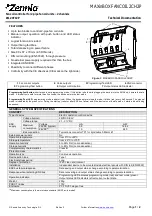
Note that in K32W041AM upgrade module board design, PIO20 is reserved for flash
reset testing, for customer applications it’s not needed and could be connected out as a
GPIO with a 0 Ohm resistor.
Figure 8 K32W041AM schematics view
6. Generic expansion board
This expansion board is available in the development kit and is compatible with Arduino
shields. They are supplied pre-fitted with Arduino-compatible header of Carrier Boards in
the development kit.
The Generic Expansion Board has the following features:
•
Arduino-compatible expansion header (in four parts, CN1-CN4)
•
4 user-input buttons (SW1, SW2, SW3, SW4) connected to DIOs on
the K32W061/041 upgrade module board on the Carrier Board:
o
SW1 is connected to IO19
o
SW2 is connected to IO15
o
SW3 is connected to IO7
o
SW4 is connected to IO4
•
4 LEDs (D1, D2, D3, D4) connected to DIOs on the K32W061/041
upgrade module board on the Carrier Board:
o
D1 is connected to IO16