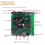
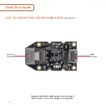
NXP Semiconductors i.MX 8M Nano Quick Start Manual Download Page 8


Quick Start Guide

SETTING UP THE SYSTEM

The following will describe how to run 
the pre-loaded Android image on the 
i.MX 8M Nano EVK.

1

Confirm Boot 
Switches

The boot switches should be set to boot 
from the eMMC. Only SW1101[1-4] are 
used for boot. See table below

BOOT 

DEVICE

SW1101

SW1102

eMMC/uSDHC3

0100XXXXXX

XXXXXXXXXX

Note:

 1 = ON  0 = OFF   X = Don’t Care

2

Connect USB 
Debug Cable

Connect the micro-B end of a USB cable 
into debug port J1701. Connect the other 
end of the cable to a PC acting as a host 
terminal. Two UART connections will 
appear on the PC, one for M7 core, one 
for A53 core. The console print will output 
on “Enhanced COM port,” which can be 
found in “Device Manager” of the PC.

If the serial port is not recognized, 
download and install updated drivers as 
listed in the section Debug Serial Console 
below.

Open the terminal window (i.e., Hyper 
Terminal or Tera Term), choose the COM 
port number that corresponds to the 
“Enhanced COM port” or the highest 
numbered port and apply the following 
configuration.

•  Baud rate: 115200
•  Data bits: 8
•  Parity: None
•  Flow control: None

8

Summary of Contents for i.MX 8M Nano

Page 1: ...Quick Start Guide i MX 8M Nano EVK...

Page 2: ...e 1 Top view i MX 8M Nano EVK board On Off Reset IR Receiver Power Switch JTAG Expansion Connector Wi Fi BT Antenna Display MIPI DSI Camera MIPI CSI CPU Board BOOT Switches I2 C Connector USB MicroB D...

Page 3: ...3 GET TO KNOW THE i MX 8M NANO EVK CONTINUED www nxp com Figure 2 Back view i MX 8M Nano EVK board MicroSD Card Connector Audio Board Connector...

Page 4: ...Quick Start Guide 4 GET TO KNOW THE i MX 8M NANO EVK CONTINUED Figure 3 MIPI DSI to HDMI Adaptor Card included in the EVK Note Color of the adaptor card may differ Mini SAS connector HDMI connector...

Page 5: ...no applications processor with up to five cores 4 Arm Cortex A53 1 Arm Cortex M7 DDR4 16 bit 2 GB eMMC 5 1 16 GB QSPI NOR flash 32 MB Power Management IC PMIC Wi Fi 802 11a b g n ac and BT5 0 Base Boa...

Page 6: ...e USB Type C Cable Cable Assembly USB 3 0 Type C Male to Type A Male USB micro B Cable Cable Assembly USB 2 0 Type A Male to Micro B Male USB Type C to A Adapter Adapter USB 3 0 Type C Male to Type A...

Page 7: ...e website Table 3 Software and Tools ITEM DESCRIPTION Documentation Schematics layout and Gerber files i MX 8M Nano EVK Board Hardware User s Guide Quick Start Guide Hardware Design Guide Power Consum...

Page 8: ...J1701 Connect the other end of the cable to a PC acting as a host terminal Two UART connections will appear on the PC one for M7 core one for A53 core The console print will output on Enhanced COM po...

Page 9: ...Mini SAS cable connected to the mini SAS connector J5 on the MIPI DSI to HDMI accessory board Note Color may differ 4 Connect Mouse Connect the mouse to J301 USB Type C Port1 through the USB Type C t...

Page 10: ...to corresponding values as listed in Table 4 Table 4 Boot Device Settings BOOT DEVICE SW1101 SW1102 eMMC uSDHC3 0100XXXXXX XXXXXXXXXX MicroSD uSDHC2 1100XXXXXX XXXXXXXXXX QSPI NOR Flash 0110XXXXXX XX...

Page 11: ...E Use this OLED display for touchscreen support Use this camera MIPI CSI camera module for machine vision video streaming and recording ADDITIONAL INFORMATION CONTINUED SUPPORT Visit www nxp com suppo...

Page 12: ...installation If this product does cause harmful interference to radio or television reception which can be determined by turning the equipment off and on the user is encouraged to try to correct the...

Reviews: