11990-190/192
Fan Trays
18
R1.0, October 2018
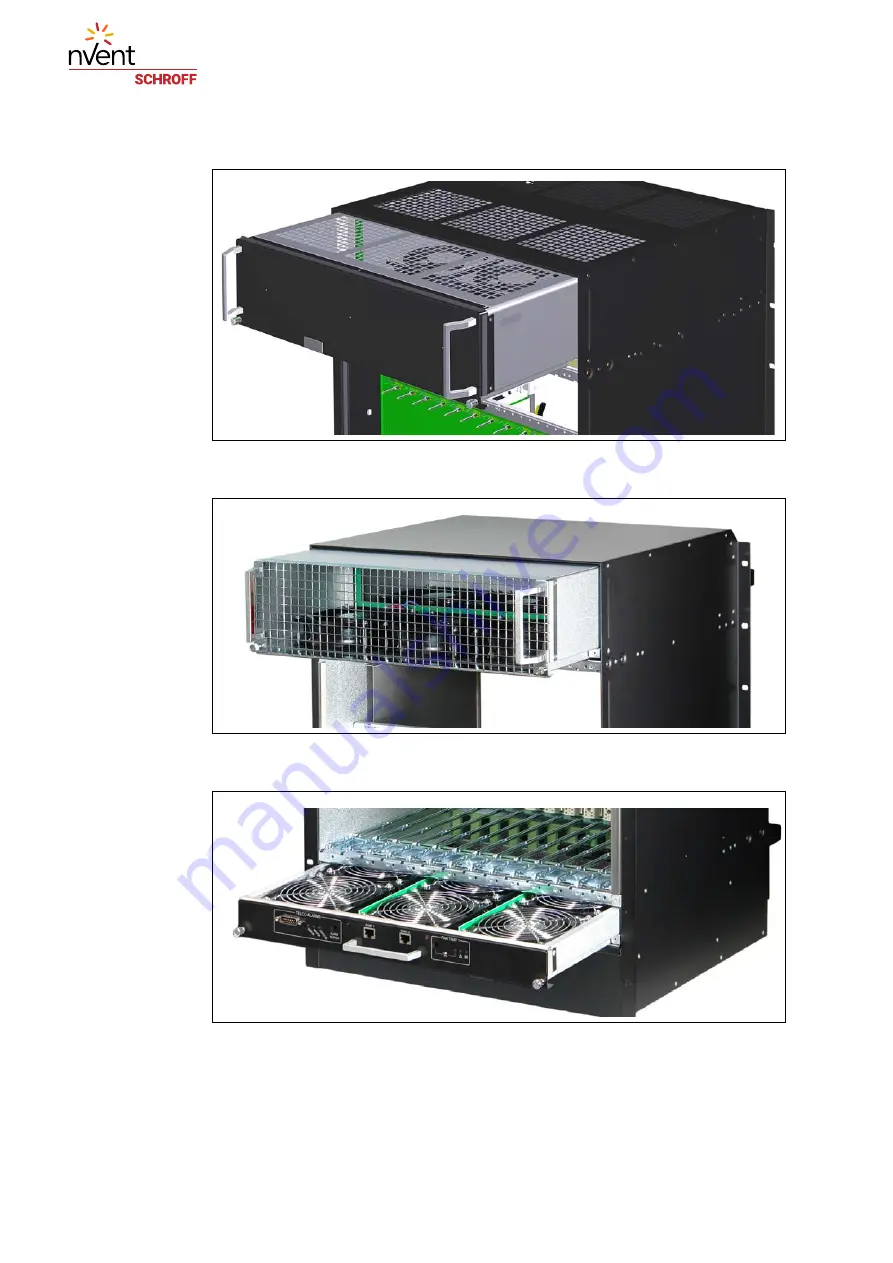
Figure 11: Upper Fan Tray 11990-190
Figure 12: Upper Fan Tray 11990-192
Figure 13: Lower Fan Tray
6.2 Maintenance/Service
We recommend a fan tray replacement every 4,5 years.
12711836
Page 1: ...14U 14 slot ATCA Shelf User Manual Product Number 11990 190 192 Doc No 63972 374_R1 0 October 2018...
Page 2: ...d by certified Quality Management System to EN ISO 9001 2000 The company cannot accept any liability for errors or misprints The company reserves the right to amendments of technical specifications du...
Page 3: ...1 Backplane Overview 10 3 2 Dedicated Shelf Manager Slots 10 3 2 1 Intelligent Platform Management Interface 11 3 3 Chassis Data Modules CDM 12 3 4 Shelf Manager Cross Connect 13 3 5 Logic Ground GND...
Page 4: ...Calculation 36 8 6 PEM Block Diagram 37 8 7 PEM Fuses 38 8 8 PEM I C bus addresses 39 8 9 PEM I O Device 39 9 Shelf Management 40 9 1 Schroff Shelf Manager ACB VI 41 9 2 Front Panel Components 43 9 3...
Page 5: ...mg com Hazardous voltage This is the electrical hazard symbol It indicates that there are dangerous voltages inside the Shelf Caution This is the user caution symbol It indicates a condition where dam...
Page 6: ...ety regulations IS 23 and IS 41 Ethernet standard IEEE standard 802 3 SNMP v3 RFCs 3413 to 3415 ROHS compliance WEEE Directive 2012 19 EU CE compliance and related regulations Schroff Shelf Manager Us...
Page 7: ...nclosure containing subrack Backplane boards cooling devices PEMs same as Shelf CMM Chassis Management Module same as Shelf Manager ECN Engineering Change Notice ESD Electrostatic Discharge ETSI Europ...
Page 8: ...nditions Airflow of minimum 65 CFM per slot will be guaranteed in all slots at maxi mum fan speed for a supply voltage of 48Vdc The cooling capability will be verified by thermal measurement acc to CP...
Page 9: ...Front and Rear View Figure 1 Shelf 11990 190 Front View 1 Front Cable Tray 6 Slot for Shelf Manger 1 2 ATCA 14 Slot Backplane 7 Shelf Manager 2 3 Front Card Cage 8 Serial Interfaces for the Shelf Mana...
Page 10: ...190 192 Hardware Platform 6 R1 0 October 2018 Figure 2 11990 190 Shelf Rear View 10 Fan Tray 2 13 Rear Cable Tray 11 Rear Card Cage 14 Power Entry Module A PEM A 12 Power Entry Module B PEM B 15 PEM...
Page 11: ...2018 Figure 3 Shelf 11990 192 Front View 1 Front Cable Tray 6 Slot for Shelf Manger 1 2 ATCA 14 Slot Backplane 7 Shelf Manager 2 3 Front Card Cage 8 Serial Interfaces for the Shelf Managers 4 Fan Tray...
Page 12: ...e located at the upper front and lower rear side of the Shelf 10 Fan Tray 2 13 Rear Cable Tray 11 Rear Card Cage 14 Power Entry Module A PEM A 12 Power Entry Module B PEM B 15 PEM Cover Danger of elec...
Page 13: ...ated Hub Slots Channels 1 2 are connected to Channel 1 2 of each Node Slot 3 0 3 Synchronization Clock Interface 6 differential pairs of synchronization clocks are bused between all 14 ATCA slots and...
Page 14: ...ACB VI Shelf Managers and are wired to IPMB A and IPMB B I C bus Base Interface Channel 1 ShMC of the Base Interface Hub slots support ing Shelf Manager Cross Connect 10 100 Base T Ethernet Fan Tray c...
Page 15: ...s and the Shelf Managers The reliability of the IPMB is improved by the addition of a second IPMB with the two IPMBs referenced as IPMB A and IPMB B IPMB A and IPMB B are routed to the ATCA slots in a...
Page 16: ...able modules and located on the rear side of the ATCA Backplane The modules can be accessed after removing the respective Power Entry Module PEM Table 2 Chassis Data Module I C addresses 12712816 1 CD...
Page 17: ...e ECN 3 0 2 0 001 This ECN adds an option for dual 10 100 Base T links from each Base Hub to both dedicated Shelf Manager slots Figure 7 Shelf Manager Cross Connect Table 3 Connector P23 pin assignmen...
Page 18: ...mechanism to connect Logic Ground GND and Shelf Ground Shelf_GND You can connect isolate Logic Ground by swapping two screws from position A to position B Screws at position A Logic Ground and Shelf G...
Page 19: ...tray can be removed by pulling the air filter s handle To re install push the air filter tray into the guide rails at each side of the shelf until the spring mounted ball lock engage Filter maintenan...
Page 20: ...3 0 conductor Recommended two hole lugs with 1 spacing for AWG 3 0 Burndy YAZ272TC38 Burndy YAZ272TC3845 45 Burndy YAZ272TC3890 90 Torque for Bolts M6 5 1 Nm 45 in lb Torque for Bolts M8 12 6 Nm 111 i...
Page 21: ...troller The Shelf Manager performs management of the Fan Tray through the two independent bussed IPMB connections When the Fan Tray is first inserted into the system the fans start at full speed and t...
Page 22: ...2 Fan Trays 18 R1 0 October 2018 Figure 11 Upper Fan Tray 11990 190 Figure 12 Upper Fan Tray 11990 192 Figure 13 Lower Fan Tray 6 2 Maintenance Service We recommend a fan tray replacement every 4 5 ye...
Page 23: ...Tray present NSEAT Short Pin HA0 HA1 Air Filter present GND GND JTAG Only in lower Fan Tray VRTN_B 48V_A 48V_B VRTN_A Fuse Monitor 48V 24V 48V 24V Hot Swap Controller PWM Tacho 48V 24V VRTN_B 48V_A 4...
Page 24: ...cates to the Shelf Managers that the Fan Tray is about to be removed Its use is optional but it is provided so that service personnel can be trained to look for a blue LED to be illuminated on any act...
Page 25: ...Hardware Reset Two relay inputs at the DB15 connector are used to reset the Minor and Major alarm state The reset inputs accept timed pulse inputs for clearing Minor and Major alarm states Reset is a...
Page 26: ...in Name Description 1 AMIR MinorReset 2 AMIR MinorReset 3 AMAR MajorReset 4 AMAR MajorReset 5 ACNO CriticalAlarm NO 6 ACNC CriticalAlarm NC 7 ACCOM CriticalAlarm COM 8 AMINO MinorAlarm NO 9 AMINC Mino...
Page 27: ...odem control is provided The serial interface is implemented on the ShMM 500 Table 7 RS 232 Serial Console Interface Pin assignment 12710848 The serial console default configuration is 115200 baud no...
Page 28: ...om to the top of the Shelf in a push pull arrangement This arrangement provides excellent airflow as well as fault tolerance in the unlikely event of a fan failure 7 1 System Airflow Path 11990 190 Fi...
Page 29: ...irflow Path 11990 192 Figure 18 System Airflow Path Overall airflow 2000 m h 1180 CFM Front slot airflow 113 m h 67 CFM at the lowest performing slot Rear slot airflow 16 m h 9 CFM at the lowest perfo...
Page 30: ...11990 190 192 Thermals 26 R1 0 October 2018 7 3 Front slot measurement zones...
Page 31: ...ront Board Air Distribution The airflow is measured with impedance boards acc to the PICMG 3 0 R3 0 specification Front board pressure drop 37 Pa at 0 85 m min Figure 19 Front Board Air Distribution 1...
Page 32: ...11990 190 192 Thermals 28 R1 0 October 2018 Figure 21 Front Board Air Distribution 11990 192 Figure 22 Front Board Air Flow 11990 192...
Page 33: ...Rear Board Air Distribution The airflow is measured with impedance boards acc to the PICMG 3 0 R3 0 specification Rear board pressure drop 24 Pa at 0 14 m min Figure 23 Rear Board Air Distribution 11...
Page 34: ...11990 190 192 Thermals 30 R1 0 October 2018 Figure 25 Rear Board Air Distribution 11990 192 Figure 26 Rear Board Air Flow 11990 192...
Page 35: ...ns of dedicated voltage monitor device The PEM provides PCA9555 I O device for voltage monitoring and Hot Swap functionality LM75 temperature sensor 24LC256 FRU SEEPROM 2 INA220B Current Voltage measu...
Page 36: ...nches supply power to a separate part of the ATCA Backplane The PEM together with all shelf related FRUs are protected against wrong polarity up to 57 V DC but it does not block wrong polarity voltage...
Page 37: ...11990 190 192 Power Entry Module PEM 33 R1 0 October 2018 8 2 PEM Front View Figure 27 PEM Front View 1 PEM Cover 2 Input Terminal...
Page 38: ...e AWG 3 0 suitable for min 90 C 194 F maximum length 3 m Recommended cable lug Panduit LCD3 0 56D X or equivalent 2 Split cable wiring Connect two cables at the 48 V and two at the RTN feed with a two...
Page 39: ...ule PEM 35 R1 0 October 2018 Figure 28 PEM Wiring PEM RTN 48 60 V Feed B Feed A RTN 48 60 V RTN 48 60 V RTN 48 60 V Feed B Feed A RTN 48 60 V Single cable wiring Split cable wiring PEM RTN 48 60 V PEM...
Page 40: ...r Branches within the Shelf 8 5 Slot Power Calculation Each branch supplies power to group of slots and or a Fan Tray or a Shelf Manager The Shelf Manager calculates the maximum branch power by the mi...
Page 41: ...11990 190 192 Power Entry Module PEM 37 R1 0 October 2018 8 6 PEM Block Diagram Figure 30 PEM Block Diagram 12711845...
Page 42: ...38 R1 0 October 2018 8 7 PEM Fuses Figure 31 PEM Fuses 12714800 F101 Fuse Branch 1 50 A 80 V F401 Fuse Branch 4 50 A 80 V F201 Fuse Branch 2 50 A 80 V F501 Fuse Branch 5 50 A 80 V F301 Fuse Branch 3 5...
Page 43: ...A9555 PEM A Right view from rear 0xa8 54 0x98 4c 0x48 24 PEM B Left view from rear 0xaa 55 0x9a 4d 0x4a 25 PCA9555 I O pin Function State 0 0 n c 0 1 Power Branch 1 after the fuse present 48 V present...
Page 44: ...he CDMs are connected to the internal I C bus on the Fan Trays The on blade Shelf Manager has access to these components via the IPM controller of the Fan Trays Figure 32 Shelf Management IPMB A B I C...
Page 45: ...management is based on the Pigeon Point Shelf management solution for AdvancedTCA products The Shelf management software runs on the Pigeon Point Shelf Management Mezzanine 700 ShMM 700R a compact 204...
Page 46: ...Management 42 R1 0 October 2018 Figure 33 Schroff Shelf Manager 12708825 1 Extraction handle 5 Backplane Connector X100 2 ShMM 700R 6 Backplane Connector X102 3 RTC backup capacitor 7 Fixing screw 4 A...
Page 47: ...of Service OOS 3 ETH 0 Link Activity LED yellow On Link Off No Link Blinking Activity 8 Shelf Manager Status LED green Solid Green in Service active Shelf Manager Blinking in Service Backup Shelf Man...
Page 48: ...nd IPMB B from the ShMM 700R are routed to the Backplane connector through I2c buffers The ATCA Backplane buses the two IPMBs to the ATCA boards The Active signal of the ShMM 700R is used to switch on...
Page 49: ...be connected to a Telecommunication Network Circuit that leaves the building The ETH0 interface of the shelf manager can manually be switched between the front panel RJ45 connector Front position of t...
Page 50: ...ger Cross Connect Table 10 Connector P23 pin assignment for Shelf Manager Cross Connect 12709823 Row Designation ab cd ef gh 5 Shelf Manager Port with Shelf Manager Cross Connects Tx1 Tx1 Rx1 Rx1 Tx2...
Page 51: ...These signals are routed through the Shelf Manager backplane connector to a RJ45 connector on the front panel of the lower Fan Tray 9 6 Front Panel RESET push button The Shelf Manager provides a RESET...
Page 52: ...Shelf Manager from a powered Shelf Table 11 Hot Swap LED 9 8 Hardware Address The Shelf Manager reads the hardware address and parity bit from the backplane connector of the Dedicated Shelf Manager s...
Page 53: ...between the ShMM 700Rs The active instance posts incremental state updates to the backup via this interface As a result the backup can quickly step into the active role if necessary The Hardware Redu...
Page 54: ...following basic commands For a full list of all CLI commands refer to the Pigeon Point Shelf Manager External Interface Reference Manual Change IP address of the primary Shelf Manager clia setlanconf...
Page 55: ...ation in a board clia fruinfo IPMI address FRU id Change the speed for a Fan Tray clia setfanlevel IPMI address Fru id speed Info The value for the speed is from 0 to 15 Display the contents of the Sy...
Page 56: ...us voltage Entity Presence 0x25 Discrete This sensor indicates the presence of the 48 V_B at the shelf manager back plane connector 10 18 0 48A ACB voltage Entity Presence 0x25 Discrete This sensor in...
Page 57: ...ger 12 22 0 48B ACB Fuse Entity Presence 0x25 Discrete This sensor indicates the state of 48 V_B input fuse on the shelf man ager 12 128 0 HWRI State OEM reserved 0xde Discrete This sensor indicates t...
Page 58: ...ensor indicates the presence of fan tray 1 lower fan tray 20 156 0 Fan Tray 2 Pres Entity Presence 0x25 Discrete This sensor indicates the presence of fan tray 2 upper fan tray 20 160 0 PEM A Voltage...
Page 59: ...link state 5a 3 0 Telco Alarm TELCO Alarm Input 0xf4 Discrete Telco alarm input sensor 5a 4 0 3 3V Voltage 0x02 Threshold This sensor measures the local 3 3 V voltage in volts 5a 5 0 3 6V External Vo...
Page 60: ...state 5c 3 0 Telco Alarm TELCO Alarm Input 0xf4 Discrete Telco alarm input sensor 5c 4 0 3 3V Voltage 0x02 Threshold This sensor measures the local 3 3 V voltage in volts 5c 5 0 3 6V External Voltage...
Page 61: ...h 6 after fan tray s main fuse 5c 21 0 48V B Branch 5 OEM reserved 0xc0 Discrete This sensor indicates the presence of the 48 V_B branch 5 at the upper fan tray connector 5c 22 0 48V B Fused 5 OEM res...
Page 62: ...5 mm The Pin Staging PS is the length of the Pins of the connector at the Backplane not at the Shelf manager a PS b PS c PS d PS e PS 1 48 V_A B VRTN_A B NC B 48 V_B B VRTN_B B 2 3 SHELF_GND B SHELF_G...
Page 63: ...5 I2C_SCL_CH1 A I2C_SCL_CH0 A UART0_RI A GND A I2C_SDA_CH3 A GND C 6 ETH0_TX A ETH0_TX A GND B USB1_DP A USB1_DM A C 7 ETH0_RX A ETH0_RX A GND B USB0_DP A USB0_DM A GND C 8 I2C_SDA_CH4 A I2C_SCL_CH4...
Page 64: ...tage FAN_PRES 0 2 Fan Tray present grounded on Fan Tray when present FAN_SPEED DC for Fan Speed Control 0 V to 10 V 10 mA FAN_TACH 0 8 Tachometer signals from Fan Trays GND logic ground HA 0 Hardware...
Page 65: ...an speed control collector UCE0 max 70 V Imax 2 mA PWM_E Opto isolated PWM signal for fan speed control emitter connected to FAN_24V_RTN on Backplane SAP_PRES Presence signal of SAP Grounded on SAP wh...
Page 66: ...wer feed is divided internally at the PEM in 6 out put branches with 35 A each Overcurrent Protection 50 A fuses on PEM Environmental Ambient temperature long term 5 C 40 C 41 F to 104 F Ambient tempe...
Page 67: ...11990 190 192 Technical Data 63 R1 0 October 2018 10 1 Shelf Mechanical Dimensions Figure 39 Shelf dimensions All dimensions are in millimeters mm...
Page 68: ...11990 190 192 Technical Data 64 R1 0 October 2018...
Page 69: ......
Page 70: ...Schroff GmbH Langenalber Str 96 100 75334 Straubenhardt Germany Tel 49 7082 794 0 Fax 49 7082 794 200...