20
|
CAUTION!
The measuring input and the USB interface are not electrically
isolated.
Do not connect the USB with a grounded sensor, even if the
ground of the PC is grounded (e.g. a desktop PC).
The device is configured, parametrized, and operated using
the four buttons on the front. A setup program is also available
for convenient configuration of the device using a PC. Some
functions can only be configured with the setup program.
The individual parameters for device setting are organized in
different levels that can be inhibited. The level inhibit helps to
prevent accidental or unauthorized operation.
4. Operation
4.1
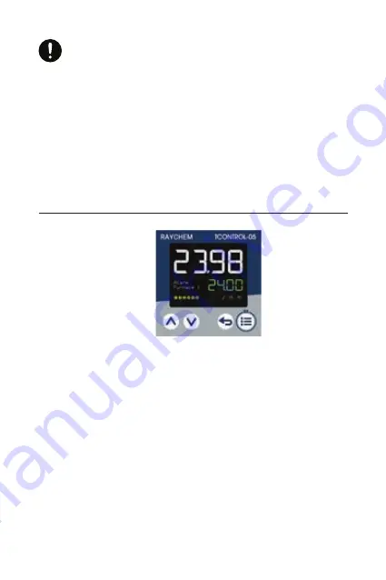
Display and control elements
1. 18-segment LCD display (e.g. actual value), 4-digit, white;
also for displaying menu items, parameters and text)
2. 18-segment LCD display (e.g. setpoint value), green; also for
displaying menu items, parameters, values and text); display
“OK” when exiting editing mode (with change)
3. Activity display for ramp function/program, timer, manual
mode
4. Switching of the digital outputs (yellow = active)
5. Up (in the menu: increase value, select previous menu item or
parameter; in basic status: increase setpoint value)
6. Down (in menu: reduce value, select next menu item or
parameter; in basic status: reduce setpoint value)
7. Back (in menu: back to previous menu level, exit editing mode
without change; in basic status: configurable function)
8. Menu/OK (call up main menu, switch to submenu/level,
switch to editing mode, exit editing mode with change)


