background image

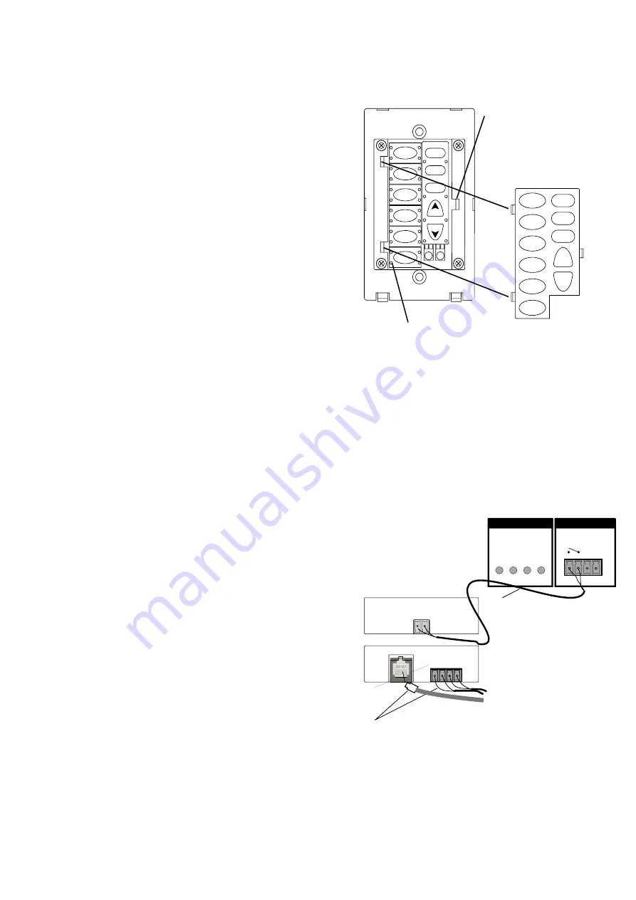
Fig. 16: Changing Keypad Buttons

XII. Changing the Buttons on the NV-EKP

XIII. NV-MI1 Mute Interface

BACK

Page 14

NV-MIB1

TO E6m

TELCO IN

The NV-EKP keypads come with 30 preprinted,

interchangeable buttons. These have a variety of audio

source labels for customizing the E Series system to match

the audio components being used. Included in these are

six genre buttons, such as Classical, Rock, Jazz, etc.

These can be useful for components like CD changers or

satellite receivers that can be set up for specific styles of

music.

The keypads have a screwless cover plate that is easily

removed with a small screwdriver. Under that plate is

another smaller plate that holds the buttons in place. This

is also easily removed with a small screwdriver. Once that

is removed, the buttons can then be replaced either

individually by tearing the perforation or as a complete

strip of six buttons.

Align the buttons you wish to use on the keypad and snap

the internal cover plate back over them. Snap the cover

plate back on, and the keypad is now ready to be installed

in its location in the wall (Fig 16).

CD 1

SAT

TUN 1

TUN 2

TUN 3

ALL OFF

ON•OFF

MUTE

VOL

VOL

CD 2

REFER TO MANUAL

0 1 2 3

DIAGNOSTIC

CONTROL

-INPUT- -OUTPUT-

MUTE UNIT ON

+12V G

The NV-MI1 Mute Interface is an additional accessory that

can be used to temporarily mute all zones whenever the

phone rings or the doorbell chimes. No external power is

needed for this purpose.

To mute the system when the doorbell chimes, simply run

a pair of doorbell wires from the chime terminals to the

connector on the MI1 labeled  “DOORBELL A” or

“DOORBELL B” (or both). Then connect a pair of wires

from the “Mute Out” jack on the MIB-1 to the “Mute” pins

on the back of the E6M amplifier (Fig. 17).

To mute the system when the phone rings, simply connect

a standard four conductor telephone line cord (for two

phone lines) into the “Telco In” jack, and then connect a

pair of wires from the “Mute Out” jack on the MIB-1 to the

“Mute In” pins on the back of the E6M amplifier (Fig. 17).

FRONT

Up to two phone lines from the home’s

telephone service can be connected

to the MI1 via typical four-conductor phone

line with an RJ11 connector. Two doorbells

can be connected to the MI1 from the

doorbell chimes using two-conductor wire.

Fig. 17: NV-MI1: Mute Interface

The MI1 will accept

two phone lines and

two doorbell signals,

and combines them

to one two-conductor

connection to the

E6M’s “Mute” input.

DOORBELL

   A         B

 I

Using a small

screwdriver, release

the tab holding the

internal cover plate to

the keypad, and

remove it.

The buttons have rubber tabs designed to

fit into holes in the keypad’s PC board.

The MI1 is not supplied with the E6M or the E6X

packages.

All manuals and user guides at all-guides.com

all-guides.com

Summary of Contents for E Series

Page 1: ...ES NV E6MS NV E6XS MULTI SOURCE MULTI ZONE AUDIO DISTRIBUTION SYSTEM OWNER S MANUAL VOL VOL TUN3 TUN2 TUN1 SAT CD2 CD1 MUTE ON OFF ALL OFF All manuals and user guides at all guides com a l l g u i d e s c o m ...

Page 2: ...ts or any other openings 15 This unit should be checked by a qualified service technician if A The power supply cord or plug has been damaged B Anything has fallen or been spilled into the unit C The unit does not operate correctly D The unit has been dropped or the enclosure damaged 16 The user should not attempt to service this equipment All service work must be done by a qualified service techn...

Page 3: ...on for the command you desire and the E Series does the rest The built in IR repeater allows for direct access to all of your audio source equipment by utilizing the individual audio component s hand held remote or you can enjoy the convenience of having all of the commands of your audio source equipment in one universal learning remote In addition the RC1 remote is the perfect tool for teaching a...

Page 4: ...emitting diode will remain lit as long as the power button is engaged Note that once the system is installed it is designed to be left on These LEDs indicate the power status of each zone Once in standby mode each zone has the ability to be powered up or down independently POWER Button Stand By LED ZoneStatusLED E Series Amplifier Front 1 2 3 All manuals and user guides at all guides com ...

Page 5: ...on is used to transfer the audio information from the E Series main amplifier to the expander amplifier This output is used to expand the system to twelve zones These outputs transfer IR signals from the zones to your source components They are routed odd and even so that when source 1 3 or 5 is selected at any of the keypads the IR outputs 1 3 and 5 all flash IR commands Similarly when source 2 4...

Page 6: ...e jack The system operates on standard EIA TIA 568A wiring This turns the entire system off from any of the zone keypads Each zone can be individually turned on or off Each zone can be individually muted The source selection button will flash indicating a muted zone The music s volume may be increased or decreased individually in each zone Infrared commands can be used to control the E Series syst...

Page 7: ...the three NUVO 3 IN 1 Tuners Use the numeric keypad to change audio sources Turn off the entire system via IR This allows IR control of the individual volume in each zone Use the RC1 remote s IR emitter to directly control the E Series system or to teach the system control functions to any learning remote control Individual zones may be turned on or off via IR Use the remote control to individuall...

Page 8: ... go from the location of a speaker to the location of the E6M amplifier These cables are terminated at the E6M using the supplied 4 pin terminal block connectors Using more than one pair of 8 ohm speakers is not recommended Doing so could overheat and damage the amplifier and will void the warranty When routing the Cat 5 and speaker cables be careful to avoid running them in parallel with any othe...

Page 9: ...esupplied10ft Cat 5cablesuppliedwiththepackage Fig 3 BothRJ45connectorsarewiredidenticallywiththe568Awiring scheme so either end is connected to the E Z Port with the opposite end connecting to the Network Input on the back of the E6M If the supplied network cable is too short or too long you can make your own using the 568A wiring scheme outlined in Fig 1 page 6 IR EMITTER OUTPUTS 12V OUTPUT PULS...

Page 10: ...es system The emitters are plugged into the IR Emitter Outputs Fig 5 Outputs 1 6 are routed to the odd and even sources In other words if source 1 3 or 5 is selected at the keypad then emitters 1 3 and 5 all flash as does the Sum output If source 2 4 or 6 is selected then emitters 2 4 and 6 all flash as does the Sum output IR source routing allows you to have two identical sources and still have i...

Page 11: ...mplifier and void the warranty Fig 6 Audiolink and Datalink Connection NV AI2 Audiolink Cable E6X Amplifier NV DI3 Datalink Cable E6M Amplifier AUDIO OUTPUT CONNECT TO NV E6X NETWORK CONNECTTO NV EZP DIGITAL OUTPUT CONNECT TO NV E6X 12V OUTPUT PULSE 1 2 3 4 5 6 SUM ODDNUMBEREDOUTPUTSAREIDENTICAL TIEDTOGETHER EVENNUMBEREDOUTPUTSAREIDENTICAL TIEDTOGETHER IR EMITTER OUTPUTS AUDIO OUTPUT DIGITAL INPUT...

Page 12: ...the speakers that are plugged into the Zone 1 speaker outputs Fig 8 Plug the keypad into the Cat 5 cable that is in zone 1 If you press the ON OFF button the keypad should light up and the LED on the front panel of the E6M amplifier for ZONE 1 should light up Fig 8 DIP switches 1 4 Zone 1 Zone 2 1 2 3 4 5 6 7 8 O N Zone 3 Zone 4 Zone 5 Zone 7 Zone 6 Zone 8 Zone 9 Zone 10 Zone 11 Zone 12 The three ...

Page 13: ... position Fig 11 Fig 11 Switch 7 Zone Grouping Zone Group ON Zone Group OFF 1 2 3 4 5 6 7 8 O N Switch 8 allows you to have the volume reset itself to a low level at power off If this switch is in the up position the audio volume will reset to a preset low level when power is restored to that zone If the switch is in the down position then the audio volume will return to its previous volume level ...

Page 14: ...page for storing the E Series internal functions i e source selection volume etc you can then easily teach these functions to your learning remote and have complete wireless control of your NUVO system NV RC1 Remote Learning Remote The Mute input can be used to mute the system by providing a dry closure to these pins Fig 14 In other words any short circuit across this input will temporarily mute t...

Page 15: ...ad is set the LEDs will continue to cycle to the next address with the flashing LEDs indicating which of the four address DIP switches should be in the down position Fig 15 Important Note Once a keypad has been addressed it should be left hooked up to the system This will keep the diagnostic LEDs accurately displaying the next available address If the MPU s bus transceiver is functioning properly ...

Page 16: ...al accessory that can be used to temporarily mute all zones whenever the phone rings or the doorbell chimes No external power is needed for this purpose To mute the system when the doorbell chimes simply run a pair of doorbell wires from the chime terminals to the connector on the MI1 labeled DOORBELL A or DOORBELL B or both Then connect a pair of wires from the Mute Out jack on the MIB 1 to the M...

Page 17: ... input shunts in any unused RCA source inputs Section IV Attaching Source Equipment to the E6M The RC1 wireless remote will not operate the E6M The RC1 is in Tuner mode or there are dead or improperly installed batteries Make sure the Device Selector switch is in the Multi room position and that the batteries are installed properly and are good Troubleshooting In certain zones the repeater does no...

Page 18: ... Unit Weight in pounds 19 0 Shipping Weight in kilograms 10 0 Shipping Weight in pounds 22 0 NUVO Technologies warrants this product to be free of defects in workmanship or material for a period of three 3 years from the original date of purchase This warranty applies to the original purchaser only and is not transferable This warranty is subject to the following conditions and exclusions Defects ...

Page 19: ...NUVO Technologies Inc 4940 Delhi Pike Cincinnati OH USA Tel 866 796 4904 Fax 513 347 2298 www nuvotechnologies com All manuals and user guides at all guides com ...

Reviews: