background image

OPI_TOP LIFT TSK 8000_V3.2_EN

23

6  Behaviour in cases of error

Defective operational readiness of the lift may be 

due to a simple error. Check the system for the list-

ed sources of error.

If the error cannot be removed after an inspection 

to the named causes, then inform customer service 

or your dealer.

 Independent repair work on safety 

devices of the lift and checking the 

electrical system may only be done 

by specialists.

Problem: Motor does not start

Possible causes:

Remedy:

No power supply

Check the power supply

The main switch is not 

switched on, or is de-

fective

Check main switch 

Defective fuse

Have fuses checked

Power supply interrupt-

ed

Inform customer service

Thermal fuse of the mo-

tor is active

Let motor cool (cooling 

time dependent on am-

bient temperature)

Motor defective

Inform customer service

Problem: Motor starts, load is not lifted

Possible causes:

Remedy:

The vehicle is too heavy Unload vehicle

Hydraulic oil filling level 

is too low

Refill hydraulic oil

The emergency dis-

charge screw is not 

closed

Check the emergency 

discharge screws

Hydraulic valve defec-

tive

Inform customer service

Mechanical pump de-

fective

Inform customer service

The coupling between 

the motor and pump is 

defective

Inform customer service

Problem: The lift cannot be lowered

Possible causes:

Remedy:

Lifting table is sitting on 

an obstacle

See Section 6.1

Hydraulic valve defec-

tive

Inform customer service

Defective fuse

Have fuses checked

Push button defective 

Check push button

6.1  Moving onto an obstacle

If the lift drive-on rail/lift arm moves onto an obstacle 

during lowering, then it remains in position due to the 

mechanical resistance. By pushing the "Lift" button, 

the lift can be raised again to remove the object.

6.2 

Emergency  discharge  with  external  unit 

and safety latch

 An emergency discharge is an ac-

cess into the lift controls and may only 

be done by experienced specialists.


The emergency discharge must be 

done in the following described se-

quence, otherwise it can lead to 

damage and hazard to life and limb. 

Any kind of external leakage is not 

permitted and must immediately tak-

en care of. This is absolutely neces-

sary especially before an emergency 

discharge.

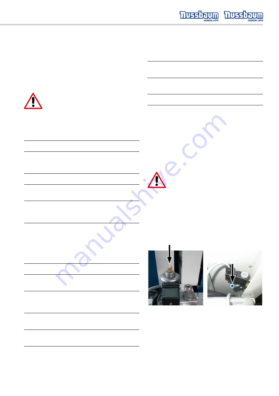
Fig. 2a (left): Hydraulic emergency lowering, re-move cap and 
open valve
Fig. 2b (right): Pneumatic air supply for actuating the ratchet 
cylinders.

6.2.1 Defect of the hydraulic valve

If there is a defect in the hydraulic valve there is still 

the option of moving the lift to its lowest position so 

the vehicle can be drive off the lift.

1.  Push the “Lower” button and the latches must 

unlock.

Summary of Contents for TSK 8000

Page 1: ...TOP LIFT TSK 8000 Serial No Operating manual Inspection book including spare parts list Version USA Manual date 29 11 2021 Made in Germany OPI_TOP LIFT TSK 8000_V3 2_EN...

Page 2: ...2 OPI_TOP LIFT TSK 8000_V3 2_EN...

Page 3: ...devices________________________________ 14 3 3 Data sheet___________________________________ 15 3 4 Foundation plan______________________________ 17 3 5 Hydraulic plan________________________________...

Page 4: ......

Page 5: ...ety manual AL ST 17 ANSI ALOIM 2008 R2013 Amer ican National Standard for Automotive Lifts Safety Requirement for Operation Inspection and Main tenance ALI WL Series ALI Uniform Warning Label Decals P...

Page 6: ...l arms The Lift must not be installed in a hazardous loca tion or in washing bays The Lift must be checked by a service technician after initial installation and after repairs or chang es have been ma...

Page 7: ...switch has been turned off and secured and the operating lever is additionally secured against unauthorised use Save these instructions 1 6 Safety devices Nussbaum has designed several saftety featur...

Page 8: ...8 OPI_TOP LIFT TSK 8000_V3 2_EN 1 7 Safety labels affixed to lift Warning Label pic tographs used with permission of Automotive Lift Institute...

Page 9: ...OPI_TOP LIFT TSK 8000_V3 2_EN 9...

Page 10: ...the completed forms in the inspection book The lift master forms must record changes to the construction or changes to set up location 1 9 Set up and test the lift Safety relevant work on the lift an...

Page 11: ...g plug to on site power supply An on site electrical connection between the lift and the power supply is to be done by a qualified electrician see details in the electrical plan The operating company...

Page 12: ..._______________________ _________________________ Date Name Signature _________________________ _____________________________________________ _________________________ Date Name Signature ____________...

Page 13: ..._________________________________________________ ______________________________________________________________________________________________________ Name address of technical expert ______________...

Page 14: ...ox 2700 psi 186 bar Pressure relief valve approx 3200 psi 220 bar Oil volume approx 4 GAL Noise level LPA 70 dB One site connection 1 N PE 230 V 60 Hz with maximum 25 Amp fuse 3 2 Safety devices Over...

Page 15: ...20 09 2019 Projektionsmethode 1 ISO 5456 2 3D CAD Modell 5 2 0 9 Die Position des Bedienaggregats kann den oertlichen Gegebenheiten angepasst werden Ggf sind die Versorgungsleitungen zu verlaengern T...

Page 16: ...16 OPI_TOP LIFT TSK 8000_V3 2_EN Clearance around the lift 2 0 2 0 2 0 2 0 recommended clearance around the lift recommended clearance between car and ceiling depends on the highest car 6...

Page 17: ...sions in mm Mass und Konstruktionsaenderungen vorbehalten dimensions and design changes reserved ind Aender modification Datum Name Zeichnungsnummer drawing number Gepr 8944_NB TSK 8000 stamp distance...

Page 18: ...1 0 B 1 1 D 1 2 S 1 3 V 1 4 K 1 5 R 2 1 Zy 2 2 Le DBV SB 1 2 1 5 1 5 1 1 P 1 T 1 3 RV1 RV2 P 2 MeP 1 4 A B 1 0 MeB MeA 0 1 SPX240 POWER UNIT 1 0 000JL21151 SB15 HYDRAULIC BLOCK COMPL 1 1 155211 RELIEF...

Page 19: ...knowledge No guarantee is made for the accuracy of enclosed circuit diagrams and switch plans contained in this document This is particularly relevant for switches that were completed by us according...

Page 20: ...20 OPI_TOP LIFT TSK 8000_V3 2_EN...

Page 21: ...1 BOX 5 CYLINDER SCREWS M16X80 10 9 9912M16X8010 9 12 PLASTIC BAG 6 CARRIAGE 2300 235TSK86003 1 BOX 7 LEDGE FOR THE LATCH COMPLETE 235TS10010 1 BOX 8 CYLINDER 235TS22100 2 BOX 9 GUIDING TUBE 235TS860...

Page 22: ...Then lower onto the locks by pushing button 3 and at the same time lift and pull the operating lever 2 The platform moves down a little and sets down in the latch When a vehicle is serviced the lift...

Page 23: ...en the motor and pump is defective Inform customer service Problem The lift cannot be lowered Possible causes Remedy Lifting table is sitting on an obstacle See Section 6 1 Hydraulic valve defec tive...

Page 24: ...ing 11 The entire lowering process must be continuous ly observed 12 Once the lift is at the lowest position the vehicle can be driven off the lift 13 The lift must be stopped until defective parts ha...

Page 25: ...o be observed during daily use Customer service must be in formed of any malfunctions 7 1 Maintenance plan i Before beginning service disconnect from power The work area around the lift is to be secur...

Page 26: ...secured so they cannot be crushed kinked or contact any moving assembly Annually 1 12 11 10 9 8 7 6 5 4 3 2 1 x 12 Trained ser vice personnel Optional energy set Electrical socket Pneumatic connection...

Page 27: ...using a sand ing cloth A 280 grit If required post treat the areas with a resistant material paint etc Annually 1 12 11 10 9 8 7 6 5 4 3 2 1 x 12 Trained ser vice personnel According to manufacturer...

Page 28: ...10 For permitted loading hoses undergo a natural change This limits the duration of use Improper storage mechanical damage and unper mitted loads are the most frequent cause of break downs The duratio...

Page 29: ...rmal specification Recommended exchange intervals 6 years operation duration including max 2 years storage time Increased demands e g by increased usage times e g multi shift short cycle times and pre...

Page 30: ...d The supply line is to be correspondingly secured on site The connec tion point is located on the electrical boxes To protect the electrical cable all cable conduits are to be fitted with cable sleev...

Page 31: ...d assembler then he can also do the safety inspection If the set up is done by the operating company then a specialist must be tasked with the safety inspection The specialist confirms seamless operat...

Page 32: ...____ Fastening screw torque ________________________________ Condition of weld seams ________________________________ Cover conditions ________________________________ Hydraulic system leak tightness...

Page 33: ...__ Fastening screw torque ________________________________ Condition of weld seams ________________________________ Cover conditions ________________________________ Hydraulic system leak tightness __...

Page 34: ...Fastening screw torque ________________________________ Condition of weld seams ________________________________ Cover conditions ________________________________ Hydraulic system leak tightness ____...

Page 35: ...Fastening screw torque ________________________________ Condition of weld seams ________________________________ Cover conditions ________________________________ Hydraulic system leak tightness ____...

Page 36: ...Fastening screw torque ________________________________ Condition of weld seams ________________________________ Cover conditions ________________________________ Hydraulic system leak tightness ____...

Page 37: ...Fastening screw torque ________________________________ Condition of weld seams ________________________________ Cover conditions ________________________________ Hydraulic system leak tightness ____...

Page 38: ...Fastening screw torque ________________________________ Condition of weld seams ________________________________ Cover conditions ________________________________ Hydraulic system leak tightness ____...

Page 39: ...Fastening screw torque ________________________________ Condition of weld seams ________________________________ Cover conditions ________________________________ Hydraulic system leak tightness ____...

Page 40: ...Fastening screw torque ________________________________ Condition of weld seams ________________________________ Cover conditions ________________________________ Hydraulic system leak tightness ____...

Page 41: ...Fastening screw torque ________________________________ Condition of weld seams ________________________________ Cover conditions ________________________________ Hydraulic system leak tightness ____...

Page 42: ...Fastening screw torque ________________________________ Condition of weld seams ________________________________ Cover conditions ________________________________ Hydraulic system leak tightness ____...

Page 43: ...tening screw torque ________________________________ Condition of weld seams ________________________________ Cover conditions ________________________________ Hydraulic system leak tightness ________...

Page 44: ...44 OPI_TOP LIFT TSK 8000_V3 2_EN...

Page 45: ...TOP LIFT TSK 8000 Serial No Made in Germany Spare parts list...

Page 46: ..._TOP LIFT TSK 8000_V3 2_EN Complete pan POS DESIGNATION 2 35 TS 2 35 R 2 35 TSK 2 35 B 1 PAN WELDED PART 235TS85003 235TSK85003 2 CUSTOM PROFILE SEAL 137785 149806 3 COVER ACCESSORIES 235TS29000 235TS...

Page 47: ...DE PIPE 235TS86000 2 BURST PIPE PROTECTION 235TS22110 3 HYDRAULIC CYLINDER 235TS22100 4 SAFETY LATCH CYLINDER 235TS02010 5 SAFETY CATCH 250TTKAS10009 6 SAFETY LATCH GUIDE 235TS30039 7 SAFETY LATCH BAR...

Page 48: ...8000_V3 2_EN Complete guide pipe POS DESIGNATION TS TSK TSK 1 GUIDE PIPE 235TS26053 235TS26053 2 CYLINDER SCREW 9912M16X60 9912M16X60 3 NUTS 9439M16ZN 9439M16ZN 4 O RING 9ORAR00433 9ORAR00433 5 GUIDE...

Page 49: ...35TSK08953 235TSK08953 3 COVER 235TSK08619 235TSK08619 4 BOLTS 235TTKA08033 235TTKA08033 5 TELESCOPE MOUNT 235TSK08980 235TSK08980 6 LOCKING PIN TELESCOPE MOUNT 250HDL48119 250HDL48119 7 LOCK WASHER 2...

Page 50: ...e 0 032 weight 22 n cket Bolts r w tubes der ssembly er Weld er 1 2 3 4 5 6 nr revision date name a New Sections 5 25 21 MB TOLERANCES UNLESS OTHERWISE SPECIFIED X 1 XX 01 XXX 005 0 25 912 M5x10 4 M5x...

Page 51: ...OPI_TOP LIFT TSK 8000_V3 2_EN 51...

Page 52: ...Dealer address phone Service Hotline Germany 0800 5288911 Service Hotline International 49180 5288911 OPI_TOP LIFT TSK 8000_V3 2_EN_122021 Artikelnummer 975540...

Reviews: