background image

Page 12

04/21/20

Champion

® 

RC300    

HAMMER ASSEMBLY


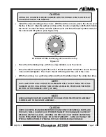
  Using the overhead crane, turn the hammer case upside down in a vertical position 

so that the bit bearing bore is facing up.


•  

Insert the bit bearing into the chuck end of the case.  This should be a close slip fit. 

Making sure the bearing makes contact with the shoulder provided for it in the case, 

insert the snap ring into the groove at the chuck end of the bit bearing diameter.


  Using the overhead crane, turn the hammer case so that the backhead end is facing 

up.  The hammer case should still be in a vertical position.


•  

Lower the piston into the backhead end of the case using the 8" (203 mm) long steel 

rods, 1.625" (41 mm) diameter steel rods and the nylon straps.


• 

Install the feed tube assembly into the backhead end of the case, making sure it is 

firmly against the shoulder in the case.  Due to close tolerances, caution is advised 

when inserting the feed tube assembly.  It should not be forced into the case.


• 

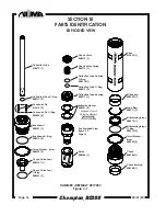
Install the belleville wahsers in the counter bore of the feed tube assembly.  See the 

stacking diagram on page 14 for proper installation.


  Install the collection tube housing o-ring and the collection tube o-ring in the I.D. of 

the collection tube housing.


  Install the collection tube housing.  The collection tube housing will rest on the belleville 

washers.


• 

Place the check valve spring and check valve on the collection tube housing.


  Install the check valve seat o-ring into the groove on the outside diameter of the check 

valve seat.


• 

  Lower the check valve seat through the check valve and check valve spring.  Make 

sure the check valve seat is seated into the collection tube housing.


  Assemble the backhead o-ring into the groove in the backhead.  Install the collection 

tube o-ring in the groove in the backhead on the drill rod mating end.  With the thrust 

washer installed on the case shoulder, thread the backhead into the case and tighten 

until the shoulder is tight against the case.


• 

  Install the connector pin o-rings on the connector pins.  Using a soft blow hammer, seat 

the (2) connector pins into the flange openings on the top of the backhead.

NOTE


DUE TO THE INTERNAL COMPRESSION SPRINGS, THE CHAMPION RC300 BACKHEAD 

CAN ONLY BE FULLY TIGHTENED WITH A POWER WRENCH ON THE RIG.

Summary of Contents for Champion RC300

Page 1: ...646 Thompson Road Thompson CT 06277 USA US Toll Free 800 356 NUMA Tel 860 923 9551 Fax 860 923 2617 E mail numa numahammers com Website www numahammers com Patents 4 530 408 4 919 221 4 962 822 5 205...

Page 2: ......
Page 3: ...Ring 3 16 Bit Retaining Rings 4 17 Thrust Washers 4 18 Chuck 4 19 Chuck Bushing 4 20 Drive Plates 4 Section II Maintenance 5 Disassembly 5 Inspection 8 General Assembly 11 Feed Tube Assembly 11 Hammer...

Page 4: ...nty period all of Numa s obligations hereunder shall terminate LIMITATION OF LIABILITY Numa shall not be liable to Buyer whether in contract in tort including negligence and strict liability under any...

Page 5: ...e most commonly used in large diameter drilling applications The Champion RC300 hammer is designed to operate using air pressure from 100 PSI to 200 PSI 6 9 Bar to 13 8 Bar with compressors having 300...

Page 6: ...een shut off The check valve in the hammer balances the hydrostatic pressure in the hole thereby preventing contaminants from entering the hammer 5 CHECK VALVE SPRING The check valve spring provides t...

Page 7: ...ousing and is designed with a long bearing surface to maintain alignment in the feed tube housing 12 PISTON The piston functions as the only moving part in the hammer controlling the operational air c...

Page 8: ...he case and one between the chuck and the case provide for easy disassembly 18 CHUCK The chuck threads into the bottom end of the case with a large cross section thread form It has internal splines th...

Page 9: ...equipped with two 1 2 UNC threads for lifting eyes The collection tube can be replaced without disassembly of the hammer Prior to removal of the collection tube pressure wash the inside diameter of th...

Page 10: ...e or lift truck move the hammer into an upright position with the chuck end down Withanadequateliftingdevice liftandsupportthehammerwhileunscrewingthe chuck After setting the hammer down and while lif...

Page 11: ...its side so that the bit end is facing you Locate the seam in the chuck bushing Insert a screwdriver into the slot in the middle of the seam and pry the chuck bushing from the under cut Remove the chu...

Page 12: ...ECK VALVE SEAT Inspect the outside diameters for nicks burrs and scoring Remove all minor irregularities with emery cloth Replace if necessary CHECK VALVE CHECK VALVE SPRING Inspect the outside diamet...

Page 13: ...y cloth Replace if necessary PISTON Inspect the striking face inside and outside diameters for nicks scoring and cracks Polish the piston with emery cloth to remove all minor irregularities Cracked pi...

Page 14: ...regularities with a file or emery cloth Replace if necessary THRUST WASHERS Inspect for damage such as cracks and deformations Replace if necessary CHUCK Inspect for cracks and burrs For continued use...

Page 15: ...ube then slide it along the feed tube until it seats against the feed tube collar Position the piston vertically Place the smallest outside diameter of the feed tube housing on the piston so that the...

Page 16: ...tube assembly See the stacking diagram on page 14 for proper installation Install the collection tube housing o ring and the collection tube o ring in the I D of the collection tube housing Install t...

Page 17: ...thread shoulder Thread the chuck into the case and hand tighten The chuck should sit flat against the end of the case With the hammer in a vertical position and the bit installed insert the collectio...

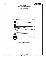
Page 18: ...915 1 Check Valve Spring 008916 1 Collection Tube Housing O Ring 008918 1 Collection Tube O Ring 008919 2 Collection Tube Housing 008917 1 Belleville Washer 008921 2 See Exploded View Figure 3 2 Page...

Page 19: ...N III PARTS IDENTIFICATION EXPLODED VIEW Feed Tube Snap Ring 008928 1 Feed Tube 008929 1 Orifice O Ring 008919 3 Feed Tube Compression Ring 008930 1 Feed Tube O Ring 008931 2 Feed Tube Housing 008912...

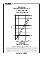
Page 20: ...FM L SEC DRILL PRESSURE BAR 6 9 10 3 13 6 17 2 DRILL PRESSURE PSI 100 150 200 250 1 2 ORIFICE O RING ORIFICE O RING INSTALLED 1 REMOVED 2 Operation Above 250 PSI 17 BAR Is Not Recommended NOTE Numa RC...

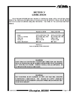
Page 21: ...exaco Caltex Rock Drill Lube 100 Rock Drill Lube 320 Chevron Vistac 150 Vistac 320 Conoco Conoco 150 Conoco 320 Numa Bio Blend RDP 150 RDP 320 Table 5 1 Recommended Rock Drill Oil CAUTION ROCK DRILL O...

Page 22: ...gn contaminants from sticking to the connector ends SHORT TERM STORAGE When the Champion hammer will be stored for only a short period of time the following steps should be taken Blow the hammer clear...

Page 23: ...environment RESTARTING Before restarting the hammer after prolonged periods of inactivity disassemble and inspect all internal hammer parts If any internal hammer parts have oxidized use an emery clo...

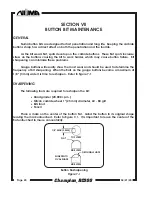
Page 24: ...the most wear and should be used to determine the frequency of bit sharpening When the flats on the gauge buttons become a maximum of 1 8 3 mm wide it is time to resharpen Refer to figure 7 1 SHARPEN...

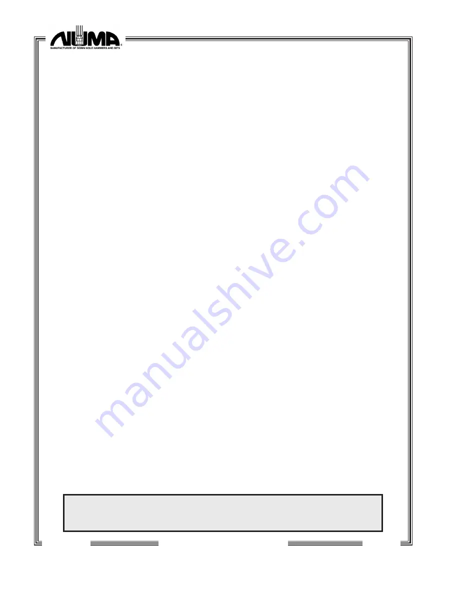
Page 25: ...Tube O Ring 008919 2 4 Collection Tube Housing 008917 0 1 Belleville Washer 008921 0 2 Feed Tube Assembly 008922 1 2 Feed Tube Snap Ring 008928 1 2 Feed Tube 008929 1 2 Orifice O Ring 008919 3 6 Feed...

Page 26: ...Page 22 04 21 20 Champion RC300 NOTES...

Page 27: ...04 21 20 Page 23 Champion RC300 NOTES...

Reviews: