16
•
Installation
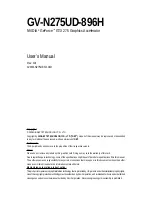
Cascaded Counters
The connection of Counter #11 and #12 are different from other
independent counters. These two counters are named as cascaded
counters because the clock sources of counter #11 come from fixed
8
MHz
and its output are cascaded to counter #12. In fact, counter
#11and #12 are designed for frequency divider by using 8254's
square wave generator mode. The gate of these counters keep at 'H'
level for enabling counters all the time. The
COUT12
can precisely
generate frequency upper to 2MHz and lower to 0.00186 Hz. Note
that the signals
C
OUT12
can also be used as interrupt source. See
‘Interrupt Sources’ section for details. The following figure
demonstrates cascaded counter - counter #11 and #12.
8 MHz
COUT11
Counter #11
COUT11
COUT12
Counter #12
8254 Chip #4
C
G
C
G
O
O
'H'
'H'
Figure 2.6 Example of ‘cascaded counter’
User Configurable Cascaded Counters
Although there is one set cascaded counter on board, users may
need more cascaded counters. User can set the clock source of
every independent counters by program. Therefore, the
independent counter output can be cascaded to the next counter's
clock source to implement cascaded counter. Figure 2.7
demonstrate an example of the user programmable cascaded
counter. Refer to next section for details of the clock source setting.
Summary of Contents for PCI-8554
Page 1: ...NuDAQ PCI 8554 Multi functions Counter Timer Card User s Guide Recycled Paper...
Page 2: ......
Page 8: ......