background image

Nu-Air Ventilation Systems Inc. - HRV Operating & Installation Manual 

 
Rev. 2.3 Aug. 19, 2014 


- 10 - 

In addition ASHRAE Standard 62-99 recommends the following.  Ventilation systems should be 
designed to prevent the reintroduction of exhaust contaminants, condensation or freeze-ups and growth 
of microorganisms.  Make-up air inlets and exhaust air outlets shall be located to avoid contamination of 
the makeup air.  Contaminants from sources such as cooling towers, sanitary vents, vehicular exhaust, 
and street traffic should be avoided.  Consult local code requirements for minimum distances.  
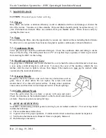
 

3.4.


Mounting & Noise Control 


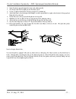
For  maximum  efficiency,  the  HRV  should  be  installed  in  a  heated 
area. The HRV is designed to be hung from the ceiling by way of the 
anti-vibration straps supplied.  Avoid hanging the HRV directly below 
a bedroom or other quiet area. 


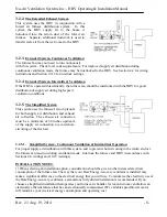
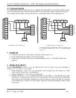
Connecting To Other Equipment - Residential Applications 

 
Interconnection with a forced air furnace duct system is 
permissible (see Section 4.4); however, your 

Nu-Air

 HRV is not 

intended to be connected to any other equipment or appliances.   
 
Flexible ducting may be desired in some installations for noise 
abatement. 

To ensure effective air flow, use only as much 

flexible ducting as necessary and keep it taut.


3.5.


 Ductwork 

 
An engineer or other qualified person should design the duct 
system.  

Duct runs should be straight with minimum bends and elbows. 

Ensure joints are tight-fitting and sealed with duct tape or sealer.   

Use galvanized duct whenever possible. Although flexible duct 

can be used, its use should be restricted to areas indicated (to 
outside hoods and in unheated spaces). 

All ducting must be supported every 3’ or less. 

Be sure to seal all pipe joints with foil tape or a duct sealant.   

When possible, form elbow joints so that they are as straight as 

possible. 

3.6.


 Drain Connections 

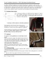
Access  to  a  drain  or  sump  is  required  to  handle  the  HRV  condensate.    Care  should  be  taken  to  run  the 
condensate tube where it cannot freeze.   
For best results, 

Nu-Air

 recommends the following steps be followed when installing drain kits on residential 

HRV's. 
1.


Apply the rubber O-ring supplied to the flange of each drain spout (A) 

Summary of Contents for WINDSOR SERIES

Page 1: ...ES O OP PE ER RA AT TI IN NG G M MA AI IN NT TA AI IN NI IN NG G I IN NS ST TA AL LL LI IN NG G Y YO OU UR R H HE EA AT T R RE EC CO OV VE ER RY Y V VE EN NT TI IL LA AT TO OR R FOR MODELS NU145 NU165...

Page 2: ...ommended or in a space manner where maintenance and service might a pose risk of personal injury or damage to this product For indoor installations only Your H ERV is equipped with a 3 prong plug whic...

Page 3: ...Other 24 V Control Options 17 4 4 Furnace Interlock 18 5 START UP 18 6 OPERATING HINTS 18 7 MAINTENANCE 19 7 5 Filters 19 7 6 Fans 19 7 7 Condensate Drain 19 7 8 Heat Energy Recovery Core 19 7 9 Exter...

Page 4: ...RECOVERY SENSIBLE in wg Pa cfm l s cfm l s cfm l s F C cfm l s Watts EFFICIENCY EFFECTIVENESS 0 1 25 173 81 180 84 193 91 32 0 61 29 54 63 75 0 2 50 159 75 165 78 175 82 32 0 85 40 66 62 72 0 3 75 14...

Page 5: ...TIVENESS 0 1 25 143 67 144 68 174 82 32 0 64 30 50 71 80 0 2 50 124 58 125 59 150 71 32 0 96 45 80 64 73 0 3 75 109 51 110 52 135 64 32 0 116 55 90 63 70 0 4 100 100 47 101 48 122 58 0 5 125 92 43 93...

Page 6: ...133 32 0 65 31 72 70 81 0 2 50 203 96 206 97 262 124 32 0 97 46 82 66 74 0 3 75 194 92 196 93 244 115 32 0 107 51 86 65 73 0 4 100 177 84 179 84 222 105 0 5 125 162 77 164 78 206 97 13 25 91 43 89 62...

Page 7: ...in both high and low speed Removable terminal blocks for timers remote controls furnace interlock A 4 wire terminal block for 12 VDC ES Series controls and a 10 wire terminal block for 24 V controls...

Page 8: ...entilation Systems 0 3 air change per hour is no longer used Areas typically serviced by Fresh Air Bedrooms Living Rooms Dining Areas and Recreation Areas Areas typically serviced by Exhaust Air Laund...

Page 9: ...n plenum for both supply air distribution and exhaust air collection The exhaust air connection must be a minimum of 40 inches upstream of the supply air connection to avoid short circuiting of the fr...

Page 10: ...s This will help avoid condensation problems and energy losses The minimum RSI value of insulation should equal that of the local building codes 3 3 1 Weather Hood Installation 1 Insulated flex duct s...

Page 11: ...4 however your Nu Air HRV is not intended to be connected to any other equipment or appliances Flexible ducting may be desired in some installations for noise abatement To ensure effective air flow u...

Page 12: ...in the drawings below 8 Attach the free end of the hose to the left fitting Repeat for the other side 9 Use the remaining hose to form a P trap and terminate at the top of the tee 10 Pour approximate...

Page 13: ...UST air pushbuttons not both for 3 Seconds Releasing the push button places the unit in SPEED ADJUST MODE 3 Now press the corresponding pushbutton to adjust the fresh air fan or the exhaust fan thereb...

Page 14: ...needle of the magnehelic gauge should read positively Switch hose connections if the needle falls below zero 3 Record reading from gauge and adjust the motor speed to the desired CFM 4 Repeat the proc...

Page 15: ...efrost frequency and duration based on outdoor temperature 5 C 23 F 15 C 5 F 20 C 4 F and 27 C 17 F 5th Port Recirculation and Defrost A temperature sensor is located in the fresh air stream before th...

Page 16: ...ch mode of operation the HRV ERV is operating in ES Series controls can be used in any combination and in virtually any number and can be wired in series or in parallel The user may toggle through and...

Page 17: ...for a command 3 Lo Unit operates in low speed continuously 4 Rec Unit operates in full time recirculation Hi with no outdoor air exchange 4 2 7 ES DVC The ES DVC offers a complete package of control...

Page 18: ...operator can select three operating modes See Section 10 16 for wiring diagram 1 OFF disables all functions 2 STANDBY HRV is on standby intermittent High speed ventilation on demand from the dehumidis...

Page 19: ...tion 40 50 is recommended Lower settings may be necessary in colder zones to keep windows free of condensation Spring Fall Operation 50 60 is recommended Summer Operation For air conditioned homes run...

Page 20: ...pylene or aluminum core located behind the cover should be removed and cleaned at least once a year using a mild detergent in cold water To remove the cover of the machine unlatch the two latches slid...

Page 21: ...ance HRV Check integral damper install back draft dampers as needed Check defrost system Note minimal frost build up is expected on cores before unit initiates defrost cycle function The supply air fe...

Page 22: ...u Air Ventilation Systems Inc HRV Operating Installation Manual Rev 2 3 Aug 19 2014 21 10 ELECTRICAL SCHEMATICS 10 11 ES Series Wiring Diagrams NU165 NU145 p n 50321 NA HRV rev F p n 50321 NA HRV rev...

Page 23: ...10 12 Altering Furnace Interlock Settings Depending on local Building Codes you may choose to interlock whenever the HRV ERV is operating at any speed or just high speed Position 5 interlock at any H...

Page 24: ...l short circuit and destroy the ES wall control processor Notes 1 ES controls can be connected in SERIES or PARALLEL 2 ES Controls can be used in installations where any of the 24V control options dis...

Page 25: ...the following operating modes 1 Off 2 Standby 3 Continuous low speed 4 Intermittent high speed 5 Continuous high speed CONSTANT DSTAT 1 For intermittent high speed operation connect Nu Air PN DSTAT 1...

Page 26: ...removable terminal block UNIT 24 VAC REMOVABLE TERMINAL BLOCK NC I NO R C TL TS SB Hi LO PWR red LED yellow SWITCH black WIN 20 Up to 6 Win 20 timers may run off of one system WIN 20 can be combined...

Page 27: ...NU AIR Heat Recovery Ventilator fails due to a defect in material or workmanship NU AIR Ventilation Systems Inc will supply a new core FOB Factory to replace the defective part Delivery and labour co...

Page 28: ...Windsor Nova Scotia 16 Nelson St P O Box 2758 B0N 2T0 Canada Ph 902 798 2261 Fax 902 798 2557 Email nuair nu airventilation com Web www nu airventilation com...

Page 29: ...i pour une raison fortuite nous devoins vous faire parvenir un avis de r paration ou de rappel du produit P PR RO OD DU UC CT T W WA AR RR RA AN NT TY Y R RE EG GI IS ST TR RA AT TI IO ON N C CA AR RT...

Reviews: