Page
4
of
29
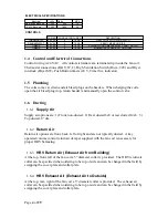
ELECTRICAL SPECIFICATIONS
Electrical
Volts
Watts
MCA
No Electric Back up
120/1
400
15
1.5 kW Back up
120/1
1900
20
CONTROLS
POWER
CONDUCTOR WIRES
THERMOSTAT
24 VAC
4
18 GA
DEHUMIDISTAT
24 VAC
2
18 GA
TIMERS
24 VAC
2
18 GA
TIMERS
24 VAC
3
18 GA
SPRING WOUND MECHANICAL COUNT DOWN
20-80% MAKE ON RISE
DESCRIPTION
HEAT COOL WITH FAN SWITCH
MOMENTARY PUSH BUTTON WIN20
Control and Electrical Connections
1.4
Control wiring is 24 VAC. All controls terminate at a terminal strip inside the fan coil.
Thermostat connections (R,G,Y,W,C), High Ventilation Switch (Hum , 24V) and Dryer
interlock (Dryer SW), Push Button timers (24 V, Timer Sw, indicator).
Plumbing
1.5
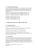
The coils come c/w drain and air bleed plugs on the headers. When charging the coils,
open the air bleed plug (top, return header) and manually open the control valve.
Ducting
1.6
Supply Air
1.6.1
Supply air options are: 1) Front, non-ducted. 2) Rear ducted 6x8 or rear ducted 14x8. 3)
Top ducted, 8” dia.
Return Air
1.6.2
Return air options are front, back, left or right and are not typically ducted. A key
operated volume control return air damper supplied with the fan coil is necessary for
proper HRV balancing.
HRV Return Air (Exhaust Air from Building)
1.6.3
At the top, front, left of the fan coil a 5” diameter collar is provided. The HRV return air
collar can be specified when ordering to be top or side and can be changed in the field by
swapping the cover plate and collar plate.
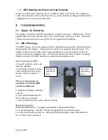
HRV Exhaust Air (Exhaust Air to Outside)
1.6.4
At the top, rear, right of the fan coil a 5” diameter collar is provided. The exhaust air
collar can be specified when ordering to be top or side and can be changed in the field by
swapping the cover plate and collar plate.
Summary of Contents for Enerboss 400C Series
Page 20: ...Page 20 of 29...
Page 21: ...Page 21 of 29...
Page 22: ...Page 22 of 29...
Page 23: ...Page 23 of 29...
Page 24: ...Page 24 of 29...
Page 26: ...Page 26 of 29...
Page 27: ...Page 27 of 29...
Page 29: ...Page 29 of 29 400C Fan Coil...

