background image


Page 

17

 of 

29


6.4


Fan Curves 

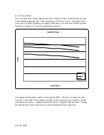
The room fan coil is usually designed for free air delivery into a room but may be used 
with minimal ducting having a static resistance of 0.25 inwc or less.  The supply fan is 
powered by an ECM operating in constant CFM mode.  The delivered airflow remains 
relatively constant over varying external static pressures 


The supply fan also draws outside air through the HRV.  The ratio of outside air and 
return air is governed by the relative amounts of static pressure in the return air stream 
and outside air stream.  A dampered return air grille is supplied with each unit.  Closing 
this damper will create more return air static and result in more outside air.  

C

FM


ESP (inwc) 

SUPPLY FAN 

C409

C412

C418

Summary of Contents for Enerboss 400C Series

Page 1: ...July 5 2011 Enerboss 400C Series Vertical Fan Coil Specifications Installation Operation and Maintenance Manual...

Page 2: ...ral Description 8 3 1 Thermostat 9 3 2 Dehumidistat Control Optional 9 3 3 24V Push Button Timers Optional 10 3 4 Recommended Seasonal Settings 11 3 5 4 MAINTENANCE 12 Maintaining Return Filters and H...

Page 3: ...mating risers and insulate the remaining copper on the supply and return water risers Shim the fan coil plumb and level if necessary Framing 1 2 Using nominal 2 studs frame around the fan coil rough...

Page 4: ...the air bleed plug top return header and manually open the control valve Ducting 1 6 Supply Air 1 6 1 Supply air options are 1 Front non ducted 2 Rear ducted 6x8 or rear ducted 14x8 3 Top ducted 8 di...

Page 5: ...ers The damper in the return air grille can be closed partially to increase outside air flow or opened to decrease outside air flow If outside air needs to be further reduced a sliding damper located...

Page 6: ...de Air High Speed Adjustment If the outside air flow is too low gradually close the return air grille damper A until the desired OA flow is measured If the outside air flow is too high gradually close...

Page 7: ...t air from building low speed flow Use the lower pot to adjust the exhaust fan LOW speed Turn clockwise to increase and counterclockwise to decrease CFM Adjust until the flow matches that of the outsi...

Page 8: ...Description 3 1 The Enerboss Integrated Fan Coil has two fans The main fan circulates air in the space and also brings in fresh air from outdoors A smaller fan serves to exhaust air from the space HRV...

Page 9: ...will turn off once the call is satisfied Low ventilation only occurs on a call for heat or cool FAN ON continuous The Enerboss will constantly circulate air on low speed and ventilate continuously in...

Page 10: ...midity is above the dehumidistat set point the HRV runs in high speed The HRV fan and the main blower will operate in high speed 24V Push Button Timers Optional 3 4 Twenty minute timers Part WIN 20 ma...

Page 11: ...ilation will take place when the dehumidistat set point is exceeded After the dehumidistat is satisfied the main blower will return to low circulating warm air throughout the home while exchanging a s...

Page 12: ...er cover by lifting and tilting the top outward 3 Place the new filter in the filter brackets on the coil plate with the wire mesh toward the coil The HRV ERV Filters 4 1 2 Remove the finished panels...

Page 13: ...roduct NU AIR Ventilation Systems Inc will supply a new or rebuilt part FOB factory to replace the defective part Delivery installation and labor cost would be your responsibility Warranty Limitations...

Page 14: ...xhaust Air Out C4 09 3 4 Ton 15 2 Pipe Electric back up BK Back 0 None F Front A Front 0 No H ERV 0 none 0 none 0 none 0 none 12 1 Ton 20 2 Pipe RR Right Rear 2 2 Way B Back B Back P Poly 1 105 cfm T...

Page 15: ...0 80 80 70 70 70 70 70 70 70 70 70 ENTERING AIR WET BULB F 67 67 67 60 60 60 60 60 60 60 60 60 LEAVING AIR DRY BULB F 56 1 56 2 54 1 162 145 111 161 145 111 171 152 115 LEAVING AIR WET BULB F 56 56 54...

Page 16: ...70 70 70 70 70 70 70 ENTERING AIR WET BULB 60 60 60 60 60 60 60 60 60 60 60 60 60 60 60 60 60 60 LEAVING AIR DRY BULB 137 5 122 90 9 130 9 116 8 88 6 128 1 114 6 87 7 122 7 106 7 90 4 117 2 102 6 88 1...

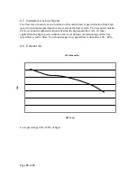
Page 17: ...ivered airflow remains relatively constant over varying external static pressures The supply fan also draws outside air through the HRV The ratio of outside air and return air is governed by the relat...

Page 18: ...ser extent the duct system The low speed outside air flow cannot be adjusted without affecting the high speed flow rate In most applications the high speed ventilation rate is set during commissioning...

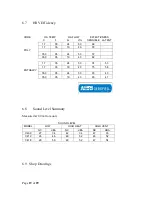
Page 19: ...0 78 35 0 95 24 50 72 35 0 95 19 40 82 ENTHALPY 1 7 35 24 50 74 53 1 7 35 19 40 75 58 35 0 95 24 50 83 43 35 0 95 19 40 85 47 6 8 Sound Level Summary Measured at 2 0 m from unit SOUND LEVEL MODEL LOW...

Page 20: ...Page 20 of 29...

Page 21: ...Page 21 of 29...

Page 22: ...Page 22 of 29...

Page 23: ...Page 23 of 29...

Page 24: ...Page 24 of 29...

Page 25: ...ack up 120 1 1900 20 CONTROLS POWER CONDUCTOR WIRES THERMOSTAT 24 VAC 4 18 GA DEHUMIDISTAT 24 VAC 2 18 GA TIMERS 24 VAC 2 18 GA TIMERS 24 VAC 3 18 GA SPRING WOUND MECHANICAL COUNT DOWN 20 80 MAKE ON R...

Page 26: ...Page 26 of 29...

Page 27: ...Page 27 of 29...

Page 28: ...h Thermister Degrees F G W Y Y Th 70 H D D Defrost Switch No calls And Not Water Control Valve Cooling Off ON Y Th 75 Y Th 75 After 5 min of valve closure if Y is still calling repeat sequence above W...

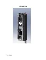
Page 29: ...Page 29 of 29 400C Fan Coil...

Reviews: