NTI SM-nXm-AV-LCD Installation And Operation Manual Download Page 9

NTI VEEMUX AUDIO/VIDEO MATRIX SWITCH 


4


INSTALLATION 

Connect the Sources 


1. 

Turn OFF power to all video sources (inputs) that will be connected to the VEEMUX-A before connecting or  

         disconnecting any cables.


2.


For each video source, connect a VEXT-xx-MM cable from the video port of the source to a video input  

        ("VIDEO 1") of the VEEMUX-A (see Fig. 1). 
3.


For each audio source, connect a SA-xx-MM cable from the audio source to an audio input ( "AUDIO IN ") port.  


Notes:


The audio port on a CPU may be marked "line out", "spkr", or "headphones".


If all 3 jacks are available, use  

            the jack marked "line out".


    The "line out" jack is typically lime green and may be marked with this symbol   
 
    The "spkr" jack is typically orange, and may be marked with this symbol  
 
   The "headphones" jack may be marked with this symbol 


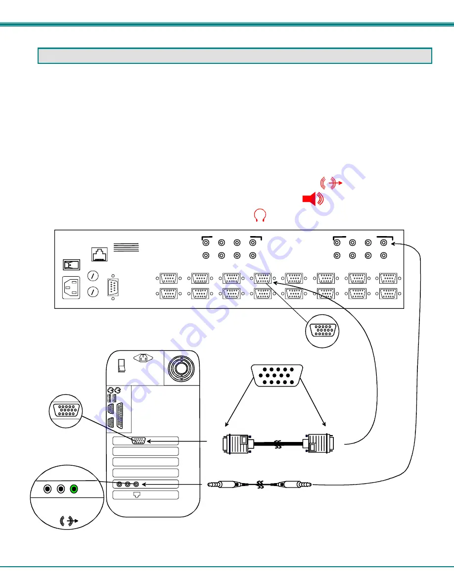
Figure 1- Install Audio and Video Source Cables 


MONITOR 1

MONITOR 2

MONITOR 3

MONITOR 4

VIDEO 1

VIDEO 2

VIDEO 3

VIDEO 4

VIDEO 5

VIDEO 6

VIDEO 7

VIDEO 8

R

S

2

3

2

MONITOR 5

MONITOR 6

MONITOR 7

MONITOR 8

NTI

NETWORK
TECHNOLOGIES
INCORPORATED

Tel:330-562-7070
Fax:330-562-1999

1275 Danner Dr
Aurora, OH 44202

  www.nti1.com

1

2

3

4

5

6

7

8

1

2

3

4

5

6

7

8

  
AUDIO IN  (CPU)

  
AUDIO OUT  (USER)

ETHERNET

Rear View of VEEMUX-A

    15HD Male
Video Connector
              

    15HD Female
Video Connector
              

    15HD Female
Video Connector
              

Video Port

Rear View of a CPU

3.5mm Stereo
      Plug

3.5mm Stereo
      Plug

SA-xx-MM

Audio Port

line
out

ONE WILL BE MARKED "line 

out" ,"spkr", "headphones" 

OR WITH THIS SYMBOL

 HD15-Male 

 HD15-Male 

VEXT-xx-MM

Summary of Contents for SM-nXm-AV-LCD

Page 1: ...014 SM nXm AV LCD Audio Video Matrix Switch Installation and Operation Manual VEEMUX A Series NETWORK TECHNOLOGIES INCORPORATED Tel 330 562 7070 Fax 330 562 1999 1275 Danner Dr Aurora OH 44202 www net...

Page 2: ...means electronic mechanical photocopying recording or otherwise without the prior written consent of Network Technologies Inc 1275 Danner Drive Aurora Ohio 44202 CHANGES The material in this guide is...

Page 3: ...2000 XP Vista and 7 13 SerTest RS232 Interface Test Program 13 Main Options 13 Matrix Operations 13 Ethernet Operations 14 Setup Options 14 Ethernet Control 14 Telnet Interface Port 2000 14 Telnet Int...

Page 4: ...ble 45 Rack Mounting Instructions 45 Specifications 46 Troubleshooting 47 Safety Statements 47 Index 47 Warranty Information 48 TABLE OF FIGURES Figure 1 Install Audio and Video Source Cables 4 Figure...

Page 5: ...iv Figure 21 Web interface Password page 33 Figure 22 Updating the Web Server 33 Figure 23 Web interface Logout page 34 Figure 24 Device Discovery Tool 35...

Page 6: ...the VEEMUX Supported Web Browsers Most modern web browsers should be supported The following browsers have been tested Microsoft Internet Explorer 6 0 or higher Netscape 7 0 or higher Mozilla FireFox...

Page 7: ...cable Connectors are 15HD male female used for OUTPUTS 3 thru 100 feet Multi coax high resolution VGA to BNC cable Connectors are 15HD male to 5 BNC s 6 feet long AUDIO SA 6 10 15 25 35 50 MM Audio In...

Page 8: ...R x 15HD female connectors for connection of video output devices 11 DDC button for manual update of DDC information between the monitor and the source s attached optional 12 LED Matrix for visual ind...

Page 9: ...marked with this symbol The spkr jack is typically orange and may be marked with this symbol The headphones jack may be marked with this symbol Figure 1 Install Audio and Video Source Cables MONITOR 1...

Page 10: ...remaining audio output devices connecting them to any remaining AUDIO OUT ports Figure 2 Install Monitors and Speakers Connect RS232 RS232 control can be achieved using a separate user terminal or CPU...

Page 11: ...l of the VEEMUX A This grid is used to provide a visual indication of all connections between video sources and destinations It is not an indication of audio connections To determine if an input video...

Page 12: ...st audio volume and configure the RS 232 control interface The keypad buttons perform the following functions ESC Escape back to the main display 0 9 Used to enter numbers OUT Specifies output port IN...

Page 13: ...ng command OUT Double digit output port number increment or decrement ENTER Ex 1 OUT 03 ENTER This will increment the volume by 6dB 2dB press Ex 2 OUT 14 ENTER This will decrement the volume by 4dB To...

Page 14: ...will switch together Independent control of video and audio ports will be disabled I e when video output 1 switches from input 1 to input 2 audio output 1 will also switch from input 1 to input 2 To c...

Page 15: ...and TXD and RXD are the only active signals A straight through DB 9 cable not null modem will work for most CPUs To daisy chain multiple units use NTI Matrix Y 1 Y cables except for the last unit conn...

Page 16: ...ge 12 for values CC SW MM CR MM CR Save Matrix Connections Into Memory Bank xx Xx 00 99 RC SW LL CR LL CR Restore Matrix Connections From Memory Bank CB 00 BR None Change baud rate of serial line BR 1...

Page 17: ...xoooo xxx CR Inspect the Scan List of individual output o skip x don t skip If the first field is not a known command as listed above or SW field is different from the serial address programmed in the...

Page 18: ...ion 1 Connect Video Output User to an Input CPU connect an output to an input 2 Connect All Video Outputs Users to an Input CPU connect all outputs to an input 3 Connect Audio Output User to an Input...

Page 19: ...PC serial port baud rate the current baud rate is displayed in parentheses 3 set unit Address current 1 select the unit address the current address is displayed in parentheses 4 set read timeout 5 sel...

Page 20: ...VV CR Read mute volume for output nn MU is 00 if the port is UNMUTED MU is 01 if the port is MUTED VV is a value between 00 to 99 see chart page 12 Ss nn dwt CR Set value of Scan Mode dwell time see...

Page 21: ...o status mode SS 00 CR CR Disable auto status mode SX CR See details Examine connections AO OP CR ac OP IP CR Read audio connection for OP AS OP IP CR CR Connect audio OP to IP AA IP CR CR Connect all...

Page 22: ...5 Byte 6 Byte 7 Byte 8 Byte 9 p 0x70 c 0x63 Space 0x20 Output 1st digit 0x30 0x32 Output 2nd digit 0x30 0x39 0x2C Input 1st digit 0x30 0x32 Input 2nd digit 0x30 0x39 CR 0x0D This command will read th...

Page 23: ...c 0x63 Space 0x20 Output 1st digit 0x30 0x32 Output 2nd digit 0x30 0x39 0x3A Input 1st digit 0x30 0x32 Input 2nd digit 0x30 0x39 CR 0x0D SS_00 Disable Auto Status Mode Command Byte 1 Byte 2 Byte 3 Byt...

Page 24: ...io input port that is connected to that audio output port AS Connect Audio Output Port to Input Port Command Byte 1 Byte 2 Byte 3 Byte 4 Byte 5 Byte 6 Byte 7 Byte 8 Byte 9 A 0x41 S 0x53 Space 0x20 Out...

Page 25: ...te 1 Byte 2 Byte 3 Byte 4 Byte 5 Byte 6 Byte 7 Byte 8 Byte 9 A 0x41 M 0x4D Space 0x20 Output 1st digit 0x30 0x32 Output 2nd digit 0x30 0x39 0x2C 0 0x30 Mute Status 0x30 or 0x31 CR 0x0D Response Byte 1...

Page 26: ...onse Byte 1 Byte 2 Byte 3 Byte 4 Byte 5 Byte 6 Byte 7 Byte 8 Byte 9 a 0x61 r 0x72 Space 0x20 Output 1st digit 0x30 0x32 Output 2nd digit 0x30 0x39 0x2C 0 0x30 Mute Status 0x30 or 0x31 0x2C Byte 10 Byt...

Page 27: ...e Accept the NTI certificate A Welcome Page will appear Figure 7 Web interface Welcome page Enter the Password Click on a link to the left to be prompted for a username and password To change the pass...

Page 28: ...e users will have full access to the Video Switch page above which displays the active connections shown in orange This page enables the user to manually control the audio and video or just the video...

Page 29: ...age 30 will disable Scan Mode for that output as configured through the LCD menu page 7 FYI See page 22 for an example of using the Outputs Scanning Sequences feature To change video only or audio and...

Page 30: ...cepted Figure 11 Web interface Audio Switch page Using the same methods of control described for the Video Switch page page 23 the user can control the audio connections made between ports on the VEEM...

Page 31: ...ebsite Timeout option controls how long an inactive web connection will stay logged in Any change to the Website Timeout configuration takes effect immediately The Telnet configuration block enables t...

Page 32: ...the same user account and password can be logged into from more than one location Note The more users that are logged in the slower the VEEMUX A will respond to changes in its settings Add User To ad...

Page 33: ...NAGEMENT section of the menu Figure 16 Edit User settings From the Edit User page the Administrator can change all user settings or delete the user altogether Just as Submit Full Access quickly provid...

Page 34: ...and only alphanumeric characters may be used Figure 17 Web interface Video Input Names page Output Names From the Administration menu the Video or Audio Output Names page can be displayed Selected se...

Page 35: ...equentially for each connected output If an input is set to 0 seconds the sequence status will display OFF and the input will be omitted from the scanning sequence To include an input in the sequence...

Page 36: ...sh a connection and starting point for the scanning sequence Blocks shown in yellow in the third image indicate connections made 3 Click on the Sequence Enable box for each output from the Video Switc...

Page 37: ...an update is attempted using the wrong firmware for the section an error message will be received No update will occur 4 Wait for the following message to appear may take several minutes Upload Succe...

Page 38: ...ord must be between 5 and 16 characters in length and can be alphabetical or numeric Help Page This page explains the purpose of each of the other pages in the VEEMUX A web interface Update Web Server...

Page 39: ...is page will enable the user to end the session and close the web interface connection Click on the Press Here to Continue Logout button to exit the VEEMUX A web interface Note The connection will tim...

Page 40: ...ll be displayed Tip If your Windows program asks which program to open the NTIDiscover jar file with select the Java program Figure 24 Device Discovery Tool Click on the Detect NTI Devices button to s...

Page 41: ...ise specified by default all IRT enabled switches will be configured as switch 1 Materials included IRT 64X32 Infrared Remote Transmitter for audio video matrix switches 2 AA Cell Batteries installed...

Page 42: ...ent switch followed by the decimal point and an error signal EE The error signal will display because there is no number to be displayed A number key must always be pressed before a SYS IN or OUT key...

Page 43: ...is larger than the maximum number of outputs the IRT is configured for then once the OUT key is pressed the LCD will display the current switch and the error signal EE Change Input Port Press the desi...

Page 44: ...he letter c will display 2 Enter the number of inputs or outputs As the digits are entered they will be displayed and the last one entered will blink Note Only the inputs OR the outputs may be configu...

Page 45: ...50 feet maximum operating range between the transmitter and the front of the NTI switch infrared receiver Note Line of sight between IRT and receiver must be unobstructed Select up to 16 outputs Sele...

Page 46: ...be connected to MONITOR 1 for this to occur The DDC information will be made available at every CPU port The DDC information can also be acquired by pressing the DDC button located on the front of th...

Page 47: ...odem cable between the serial port on the PC and the RS232 port on the VEEMUX A 3 Use HyperTerminal to prepare to connect to the VEEMUX A using settings 9600 baud 8 N 1 no flow Make sure HyperTerminal...

Page 48: ...VEEMUX A waits this is normal 7 Click Transfer Send File from the HyperTerminal menu bar 8 Select Xmodem from the Protocol drop down menu 9 Click Browse Go to the directory containing the firmware to...

Page 49: ...N a N a No connection On the DB 9 female connector pins 4 DTR and 6 DSR are shorted and pins 7 RTS and 8 CTS are shorted Therefore CPU handshaking is bypassed and TXD and RXD are the only active sign...

Page 50: ...the holes or slots in the mounting flange on the NTI switch Then secure the NTI switch to the rack using four 10 32 screws supplied Be sure to tighten all mounting screws securely Do not block power...

Page 51: ...seT RS232 Connector DB9 male 300 9600 bps Audio Connector 3 5mm jack Audio Signal Type Stereo unbalanced Audio Frequency response THD N S N Crosstalk 20Hz to 20kHz 0 5dB 0 01 1kHz 90 dB 85 dB 1kHz Aud...

Page 52: ...restored Servicing NTI products are not intended to be serviced in the field and contain no user serviceable parts In the event repair is needed all servicing must be performed by factory trained and...

Page 53: ...is two 2 years from the date of purchase Please contact Network Technologies Inc at 800 742 8324 800 RGB TECH or 330 562 7070 or visit our website at http www networktechinc com for information regar...

Reviews: