background image

Digital Video Recorder 


Chapter 3 — Configuration 


NOTE:  Your DVR should be completely installed before proceeding.  Refer to 

Chapter 2 — Installation


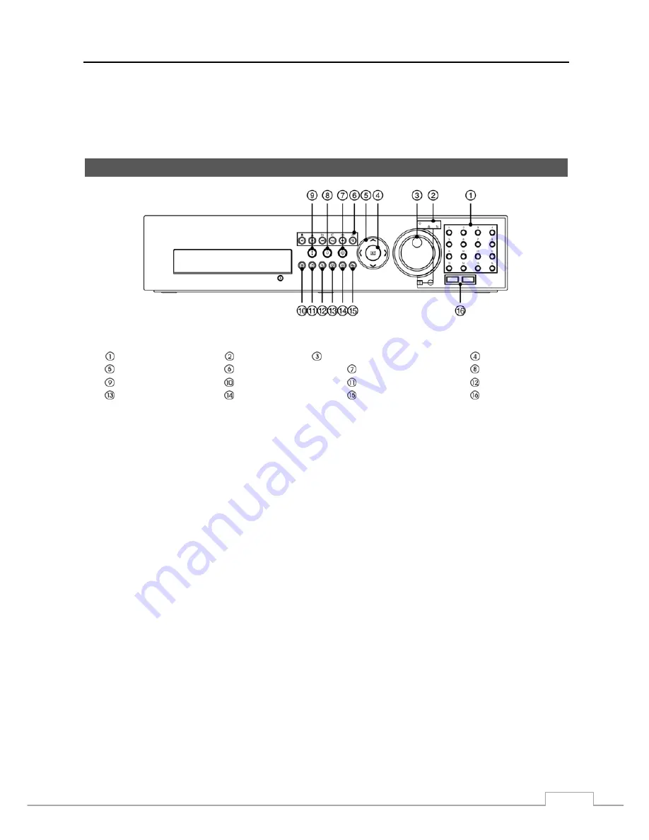
Front Panel Controls


Figure 3 :  16-Channel DVR front panel. 


Camera Buttons 


LED 


Jog Dial, Shuttle Ring 


Enter Button 


Arrow Buttons 


Playback Buttons 


PTZ Button 


Alarm Button 


Panic Button 


Freeze Button 


Bookmark Button 


Zoom Button 


Monitor Button 


Display Button 


Menu Button 


USB Port 

 
The front panel looks and operates much like a VCR combined with a multiplexer.  Many of the buttons have multiple 
functions.  The buttons on the infrared remote control, while laid out differently, perform the same functions as those 
on the front panel.  The following describes each button and control.  Take a few minutes to review the descriptions.  
You will use these to initially set up your DVR and for daily operations. 


NOTE:  The infrared sensor on the DVR is just to the left of USB ports.  Make certain that nothing blocks the 

sensor, or the remote control will not function properly. 


When you use wireless communication devices (such as Wi-Fi or Bluetooth) near the DVR, the remote 
control might not function properly. 


You can also use a USB mouse (not supplied) to navigate through the screens and menus much like you 
would on a computer. 


Summary of Contents for DVR8DVDH

Page 1: ...DVR8DVDH 512 756 1678...

Page 2: ......

Page 3: ...ERATES USES AND CAN RADIATE RADIO FREQUENCY ENERGY AND IF NOT INSTALLED AND USED IN ACCORDANCE WITH THE INSTRUCTION MANUAL MAY CAUSE HARMFUL INTERFERENCE TO RADIO COMMUNICATIONS OPERATION OF THIS EQUI...

Page 4: ...chnician to restore the equipment to its normal operation E If the equipment has been dropped or the cabinet damaged F When the equipment exhibits a distinct change in performance this indicates a nee...

Page 5: ...deo Out 6 Power Cord Connector 7 Chapter 3 Configuration 9 Front Panel Controls 9 Camera Buttons 1 to 16 10 LED 10 Jog Dial Shuttle Ring 10 Arrow Buttons 11 Enter Button 11 Playback Buttons 11 PTZ But...

Page 6: ...40 Network 42 Device Setup 42 Local Audio 42 Network Audio 43 Alarm Out 43 Remote Control 44 Display Setup 45 OSD 45 Primary Monitor 46 Secondary Monitor 48 Spot Monitor 48 Status Setup 49 Event 49 S...

Page 7: ...85 Map of Screens 89 Connector Pin Outs 90 I O Connector Pin Outs 90 RS485 Connector Pin Outs 90 System Log Notices 90 Error Code Notices 91 Troubleshooting 92 Specifications 92 List of Illustrations...

Page 8: ...screen 43 Figure 32 Device Network Audio setup screen 43 Figure 33 Device Alarm Out setup screen 44 Figure 34 Device Remote Control setup screen 45 Figure 35 Display OSD setup screen 45 Figure 36 Disp...

Page 9: ...o Playback Text Input for ATM and POS Alarm Connections Include Input Output and Reset Input Built in Alarm Buzzer Live or Recorded Video Access via Ethernet Time Synchronization using industry standa...

Page 10: ...our DVR remotely by connecting via Ethernet There are eSATA and iSCSI ports that can be used to record or archive eSATA interface only video to external hard disk drives and there are two USB ports th...

Page 11: ...tall the DVR Refer to the installation manuals for the other items that make up part of your system Figure 2 16 Channel DVR rear panel Video Input Video Loop Through Factory Reset Switch HD SD Out Sel...

Page 12: ...ect the monitor display mode between HD High Definition and SD Standard Definition Setting the selector to the HD OUT position sends HD video to the connected HDMI and VGA monitors and setting to the...

Page 13: ...ow the button After releasing the button tug gently on the wire to make certain it is connected To disconnect a wire press and hold the button above the wire and pull out the wire AI 1 to 16 Alarm In...

Page 14: ...VGA Primary Monitor connectors one of the monitors should be connected before the DVR boots and the other monitor should be connected after the DVR boots Your DVR can record audio from up to 16 sourc...

Page 15: ...INSTALL POWER CORDS UNDER RUGS OR CARPET THE POWER CORD HAS A GROUNDING PIN IF YOUR POWER OUTLET DOES NOT HAVE A GROUNDING PIN RECEPTACLE DO NOT MODIFY THE PLUG DO NOT OVERLOAD THE CIRCUIT BY PLUGGIN...

Page 16: ...User s Manual 8...

Page 17: ...ultiple functions The buttons on the infrared remote control while laid out differently perform the same functions as those on the front panel The following describes each button and control Take a fe...

Page 18: ...isk drive Jog Dial Shuttle Ring Jog Dial When in the playback mode you can play video forward image by image by turning the Jog Dial clockwise and backward image by image by turning the Jog Dial count...

Page 19: ...playing back video The button is also used for Far Focus in the PTZ mode Fast Forward Pressing the button plays video forward at high speed Pressing the button again toggles the playback speed from an...

Page 20: ...r more seconds USB Port Two USB ports on the front panel are provided to connect external hard disk or flash drives for video clip copying or system upgrades Position external drives close enough to t...

Page 21: ...to exit the screen Press the MENU button or move the mouse pointer on the right edge of the screen and then select Login in the Live Monitoring menu to enter the setup screens The Login screen appear...

Page 22: ...appear Use the arrow keys to highlight the character you want in the name or title and press the button That character appears in the title bar and the cursor moves to the next position Pressing togg...

Page 23: ...are not part of an RS485 network If this is the case all will be controlled at the same time when using the infrared remote control Highlight the box beside Language and press button A drop down menu...

Page 24: ...System Log The System Log screen lists system activities up to 5 000 from the latest that have occurred along with the time and date The icon will be displayed in the last column for system activities...

Page 25: ...ress the button The individual sections of the time will highlight Use the Up and Down arrow buttons to change the number Use the Left and Right arrow buttons to move between hour minutes and seconds...

Page 26: ...rent date appears Highlight the month and day and change them by using the Up and Down arrow buttons Press the button to add the date Dates can be deleted by highlighting the beside the date and press...

Page 27: ...iew video from cameras set as Covert while in the Live Monitoring or Search mode on a local system or a PC running RAS Search The user can access the Search mode on a local system or a PC running RAS...

Page 28: ...pace to store temporary files for CD or DVD burning by selecting Partition CD DVD Burn NOTE The DVR does NOT support USB hard disk drives with a version lower than 2 0 iSCSI devices cannot be formatte...

Page 29: ...les On and Off When set to On you can select the day time range and interval that you want the DVR to run self diagnostics on the recorder The Interval can be selectable from 1 min to 7 days or Never...

Page 30: ...E The video signal has a time difference of 1 60 second 1 50 second for PAL between odd and even fields because it is composed of 60 interlaced fields per second 50 fields for PAL When recording video...

Page 31: ...and by the type of recording mode Once the Limit Time Lapse Recording is set to On the DVR will maintain this recording limitation even after disabling the function If you want the DVR to record vide...

Page 32: ...ressed Use the No Record mode when you do NOT want the DVR to record during certain times When the DVR is in the Time mode the icon displays at the top left corner of the screen The DVR will record an...

Page 33: ...era Network Camera setup screen in this chapter and Appendix Remote Setup of Network Devices for further information on setting up the network device When recording video from network devices the arch...

Page 34: ...IF NOTE Depending on network conditions the ips quality and resolution for the network video transmitter ips for the network camera you set may not be attainable You can set the amount of time to reco...

Page 35: ...l setup screen You can limit the network bandwidth settings so that system does not consume too much network bandwidth Highlight the box beside Network Bandwidth Limit and press the Up and Down arrow...

Page 36: ...access the DVR and control it remotely using a PC or mobile devices via Ethernet Highlight the box beside Port and press the button Set the port number of the VNC server obtained from your system adm...

Page 37: ...nistrator Highlight the box beside DNS Server Press the Up and Down arrow buttons to set the IP address of the DNS server Highlight the Port Number Setup box and press the button The Port Number Setup...

Page 38: ...d by DHCP Dynamic Host Configuration Protocol network Highlight Auto Default and press the button to toggle between On and Off When it is On the DVR will obtain the IP address of the DNS server automa...

Page 39: ...button Set the port number of the DVRNS server using the Up and Down arrow buttons to increase or decrease the numbers Highlight Use NAT and press the button to toggle between On and Off NOTE When usi...

Page 40: ...access a remote DVR using a Blackberry or other mobile devices NOTE Selecting Use Mobile sets the WebGuard service to be enabled automatically regardless of your WebGuard settings When using NAT Netw...

Page 41: ...elect should be enabled in the Notification setup screen and the DVR should be registered in the RAS Remote Administration System Highlight the box beside Summary Email Interval and select the interva...

Page 42: ...of the SMTP server NOTE You will need to get the IP Address or domain name of the SMTP Server from your network administrator NOTE You can use the domain name instead of IP address if you already set...

Page 43: ...keyboard appears allowing you to enter the user name and password The SNS accounts can be deleted by highlighting the beside the account and pressing the button NOTE Posting a tweet might fail becaus...

Page 44: ...ight the box beside iSCSI CHAP Authentication and press the button An Authentication screen appears Highlight Use and press the button to toggle between On and Off Highlight the box beside User Passwo...

Page 45: ...hin the block groups are selected or cleared using the camera buttons Press the button to display the menu screen The menu on the setup screen has the following functions Select Activates highlighted...

Page 46: ...utton and the Alarm In setup screen appears Local Cameras Only Figure 25 Event Alarm In setup screen The alarm terminal strip on the back of the DVR has inputs associated with each alarm You can set u...

Page 47: ...cks to see if anything is obscuring the camera Highlight the box beside Check Obscuration and press the button A list of sensitivity ranging from 1 to 10 or Never appears The sensitivity can be set fr...

Page 48: ...an Alarm Out connector sound the DVR s internal buzzer notify a number of different devices move PTZ cameras to preset positions and or display a camera on a SPOT monitor Highlight Use Ignoring Time...

Page 49: ...s the button Use the virtual keyboard to enter the Transaction End string Refer to the device manufacturer s documentation for the text string that the device sends when a transaction ends Highlight t...

Page 50: ...ed with the DVR Highlighting the box under the Use and pressing the button turns each selected event On and Off Highlighting the box under the Actions and pressing the button selects how the DVR react...

Page 51: ...Network Audio setup screen appears Figure 32 Device Network Audio setup screen Highlight the box beside the network device input and press the button A list of local audio channels appears and you ca...

Page 52: ...Sat M F Hol and All Highlighting the boxes under the Range box and pressing the button allows you to set the time that the alarm schedule will be active in 15 minute increments from 00 00 to 24 00 Hig...

Page 53: ...e DVR Highlight the box beside Remote Control Product and select the device from the list Display Setup OSD Highlight OSD and press the button The OSD screen allows you to select what information will...

Page 54: ...the DVR can play live audio PTZ The icon displays on each PTZ camera screen Text In The text input strings display on the screen You can adjust the Display Dwell time sec for the text input strings d...

Page 55: ...080 60Hz or 50Hz for PAL video Highlight the box beside Set Resolution to Manual Mode and press the button Pressing the button toggles between On and Off When it is On you can set the resolution manua...

Page 56: ...eras will be excluded from the Cameo sequence You can define the screen layout in a variety of formats and set the DVR to sequence through the different screen layouts pages so that all the cameras wi...

Page 57: ...just the display dwell time by highlighting the box under the Dwell and pressing the button You can select dwell intervals ranging from 1 to 20 seconds Pressing the SEQUENCE button on the remote contr...

Page 58: ...tings you made in the Monitoring setup screen on the System menu Panic Record will be highlighted while the DVR is in the panic recording mode Disk Almost Full will be highlighted when the DVR is not...

Page 59: ...itions are normal however the S M A R T monitoring is not working or supported NOTE When the storage condition is Bad the Event Status Storage screen displays and you can check the storage condition f...

Page 60: ...A user who does not have Covert Camera View authority cannot view video from cameras set to Covert 1 or Covert 2 in both the live monitoring and playback modes PTZ Highlight PTZ and press the button a...

Page 61: ...rs Configure the port s setting based on the PTZ camera manufacturer s instructions Network Camera Highlight Network Camera and press the button and the Network Camera setup screen appears Network Dev...

Page 62: ...Selecting Auto Scan LAN from Mode scans network devices automatically Selecting IP Address Scan from Mode scans network devices by entering a specific IP address or adjusting the IP address range Hig...

Page 63: ...s NOTE The Settings screen will differ depending on the type of protocol that you selected The following description is for a network device using the iNEX protocol Network Device using iNEX Protocol...

Page 64: ...Remote Setup screen appears Highlight Network TCP IP Setup and press the button You can change the network settings of the network device Highlight the box beside Type and press the button You can se...

Page 65: ...tocol for streaming Highlighting the box beside Record Protocol and pressing the button allows you to select the protocol for recording Highlighting the box beside ONVIF Profile and pressing the butto...

Page 66: ...User s Manual 58...

Page 67: ...t is ready to record NOTE Depending on the monitor display mode between HD mode and SD mode the menu layout of monitor screen will be different For simplicity the menus and descriptions in this manual...

Page 68: ...352x240 352x288 704x240 704x288 640x480 704x480 704x576 800x600 1280x720 1280x960 1280x1024 and 1920x1080 When monitoring video from network devices in multiview display formats video at the resolutio...

Page 69: ...same as pressing the PTZ button Refer to the following PTZ Mode section for details Zoom Selecting Camera Menu Zoom and choosing the camera number zooms the current image of the selected camera on the...

Page 70: ...both local cameras and network devices in one monitor is not supported Zoom Mode You can enlarge an area of the video by pressing the ZOOM button For a few seconds after pressing the ZOOM button a rec...

Page 71: ...pointer at the bottom of the screen Change the toolbar location by clicking the empty space on the left side of the toolbar and drag it to where you want it located on the screen Use the arrow buttons...

Page 72: ...select the screen mode between 2x2 and 4x4 you want to display on a Spot Monitor Selecting Sequence in the Live Monitoring menu causes the cameras to display sequentially and selecting again stops seq...

Page 73: ...on will be displayed 1 image per second If a user who has Search authority logs into the system the user can view recorded image Once video has been recorded you can view it by pressing the Play Pause...

Page 74: ...d By turning the jog dial clockwise you can play video forward image by image By turning the jog dial counterclockwise you play video backward image by image Shuttle Ring The Shuttle Ring only functio...

Page 75: ...me displays the Go to the Date Time screen Move the cursor over the date and time and press the button You can use the Left and Right arrow buttons to highlight the year month day hours minutes and se...

Page 76: ...amera OSD or Status OSD On and Off Alarm Selecting Alarm in the Search menu resets the DVR s outputs including the internal buzzer during an alarm It is the same as pressing the ALARM button Panic Sel...

Page 77: ...ke to see video The Event Log Search screen can also be accessed by pressing the ALARM button unless there is an alarm There is no determined user authority to display the Event Log Search screen howe...

Page 78: ...want any reports of lost video Highlight the box beside Video Blind and press the button You can select the cameras for which you want any reports of blind video Highlight the box beside Audio Detecti...

Page 79: ...bottom switches to the Expanded view mode The Expanded view displays the recording information of each camera channel currently displayed on the screen Selecting the icon in the Standard view mode swi...

Page 80: ...hile the DVR displays the camera full screen The Motion Search screen displays a list of motion events Use the arrow buttons to highlight the event for which you would like to see video and press the...

Page 81: ...early identical to setting up the DVR for Motion Detection Please refer to Motion Setup Screen in Chapter 3 Configuration for more detailed instructions on setting up the detection blocks When setting...

Page 82: ...Highlight the box beside To and press the button to toggle between On and Off When set to Off you can enter a specific Date and Time When set to On the search will be to the last recorded image Highl...

Page 83: ...button on the remote control during playback will set the starting point of the video to be clip copied and the icon displays at the bottom left corner of the screen Selecting A B Clip Copy in the Sea...

Page 84: ...ber for example 01 and exe to the file name NOTE When naming a file you cannot use the following characters Highlight Include Text In Data and press the button This will toggle between On and Off When...

Page 85: ...rmat the hard disk drive Print You can print images on a printer Connect a PostScript printer or external hard disk drive or flash drive to one of the USB ports Highlight the box beside Printer Model...

Page 86: ...isk will be erased and the data on the source disk will be copied to the destination disk If the source disk is formatted and has no data the disks will not be resynchronized Resynchronization takes a...

Page 87: ...ated region of the USB hard disk drive Then click Create Partition 6 In the Create Partition wizard click Next then Primary Partition and follow the instructions on the screen Make sure that the FAT32...

Page 88: ...mparison value is located at 17th Unit price mark will be ignored automatically 28th Qty and 40th amount characters including spaces from the left but the value of amount category is located on a diff...

Page 89: ...mode You will need to enter the DVR IP address in the DVR ADDRESS field when running the WebGuard program by entering http www dvronline net Selecting the Use DVRNS option allows you to enter the DVR...

Page 90: ...with elevated administrator permissions Restart your computer to apply the changes Web Monitoring Mode WebWatch is a remote web monitoring program that allows you to monitor live video transmitted in...

Page 91: ...ng both and allows two way communication Clicking the disables audio communication Aspect Ratio Changes the image aspect ratio Deinterlacing Using a deinterlace filter for interlaced video enhances im...

Page 92: ...the screen Click the to save any video clip of recorded data as an executable file Click the to save the current image in a bitmap or JPEG file format Click the to print the current image on a printe...

Page 93: ...om four o clock of the first segment to five o clock of the first segment From four o clock of the first segment to five o clock of the second segment From four o clock of the second segment to five o...

Page 94: ...Manual 86 System Setup Information Displays the device information Maintenance Restarts the device or returns all device settings to the original factory settings Security Setup User Adds or deletes...

Page 95: ...es an ONVIFTM profile Video Sets up the video source and encoder The frame rate cannot exceed 15 ips when recording video with the H 264 codec and 4CIF resolution if the device is a network video tran...

Page 96: ...or the current network conditions supported only for devices that provide the function Network Protocol Changes the port numbers for the network protocols that are used in the device supported only fo...

Page 97: ...Digital Video Recorder 89 Map of Screens...

Page 98: ...pgrade Schedule On Clip Copy Camera Upgrade Fail Schedule Off Callback Fail Power Failure Panic On Print Begin Time Change Panic Off Print End Time Zone Change Clear All Data Print Cancel Time Sync Cl...

Page 99: ...Burning is out of time 402 Copying upgrade package on the USB device failed 19 Connecting device failed 403 USB device is not connected 20 Device is busy 404 USB device is being used 21 Unsupported fi...

Page 100: ...e DVR has stopped recording If hard disk drive is full you will either need to delete video or set the DVR to the Overwrite Mode The icon displays however the DVR is not recording When the DVR is in t...

Page 101: ...ps 1Gbps Ethernet Audio Output RCA Output 1 Line Out Text Input POS Interface ATM Interface CONNECTORS Video Input Composite 8 or 16 BNC Ethernet 8 or 16 network devices Video Loop Composite 8 or 16 B...

Page 102: ...Temperature 41 F to 104 F 5 C to 40 C Operating Humidity 0 to 90 Power 100 to 240 VAC 2 0 1 0 A 50 60Hz Power Consumption Max 100W Approvals FCC UL CB CE CAUTION Risk of Explosion if Battery is replac...

Reviews: