background image

DPA-2FS User Manual 


version 2.0 


page 9 

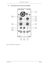
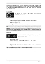
In  the  following  description  of  the  front  panel  elements  each  element  has  a  number  that  is 
related to that in Figure 5. The number is followed by the name (in uppercase letters) written 
on the front panel and the type of the element (in lowercase letters). Then, a short description 
of the element is given. 

 
OFFSET unit 

 
The  OFFSET  unit  consists  of  (1)  OFFSET  range  switch  and 
(2) OFFSET potentiometer. 


(1) OFFSET range switch 

3-position switch for selecting the OFFSET range, 

±

0.1 V, 

±

1 V or 

±

10 V. 


(2) OFFSET potentiometer 

10-turn potentiometer for compensating for a DC OFFSET. 
 

Note: The overall OFFSET compensation is the product of the reading of both controls. 
 
Important:  Position  5  of  the  OFFSET  potentiometer  corresponds  to  0  mV  offset. The offset 
compensation only works if the input coupling switch is set to DC. If the HIGHPASS FILTER 
is used, the OFFSET control is disabled. 
 
GAIN unit 


The  GAIN  unit  consists  of  (3)  GAIN  range  switch  and 
(4) GAIN factors switch. 


(3) GAIN range switch 

3-position rotary switch for selecting the GAIN range, x1, x10 or x100. 
 
(4) GAIN factor switch 

7-position  rotary switch for selecting the GAIN factor, x1, x2, x5, x10, x20, x50 or 
x100. 

 
Note: The overall GAIN is the product of the reading of both controls. 
 

Summary of Contents for DPA-2FS

Page 1: ...FOR THE DPA 2FS DIFFERENTIAL AMPLIFIER FILTER MODULE FOR EPMS SYSTEMS VERSION 2 0 npi 2015 npi electronic GmbH Bauhofring 16 D 71732 Tamm Germany Phone 49 0 7141 9730230 Fax 49 0 7141 9730240 support...

Page 2: ...S E 07 Housing 4 2 5 EPMS 03 5 2 6 PWR 03D 5 2 7 System Grounding 6 EPMS 07 EPMS 03 6 EPMS E 07 6 2 8 Technical Data 6 EPMS 07 EPMS E 07 and EPMS H 07 6 EPMS 07 and EPMS H 07 6 EPMS E 07 6 EPMS 03 6 3...

Page 3: ...efore connecting any system to mains Always use a three wire line cord and a mains power plug with a protection contact connected to ground protective earth Before opening the cabinet unplug the instr...

Page 4: ...ems are shipped with the EPMS 07 housing EPMS 07 cabinet with built in power supply Mains cord Fuse 2 A 1 A slow inserted Front covers Figure 1 Left front view of empty EPMS 07 housing In order to avo...

Page 5: ...wer supply unit the power switch and the fuse are located at the rear of the housing see Figure 2 right 2 6 PWR 03D The external power supply PWR 03D is capable of driving up to 3 EPMS E housings Each...

Page 6: ...to the SYSTEM GROUND SIGNAL GROUND on the rear panel of the instrument see Figure 4 The chassis can be linked to PROTECTIVE EARTH by connecting it to the PWR 03D with the supplied 6 pole cable and by...

Page 7: ...nce is 10 M Thus the module can be used for direct recording of bioelectric signals e g from peripheral nerves Using the differential input configuration common mode signals and noise are removed allo...

Page 8: ...DPA 2FS User Manual version 2 0 page 8 3 4 Description of the Front Panel and Operation Figure 5 DPA 2FS front panel view...

Page 9: ...OFFSET potentiometer 10 turn potentiometer for compensating for a DC OFFSET Note The overall OFFSET compensation is the product of the reading of both controls Important Position 5 of the OFFSET poten...

Page 10: ...LEDs indicating that the DPA 2FS exceeds its linear range 10 V 7 OUT connector BNC connector providing the conditioned signal 8 9 IN IN connector BNC connectors for connecting the input signal The in...

Page 11: ...i 15 1641 1645 Huemmeke M Eysel U T Mittmann T 2004 Lesion induced enhancement of LTP in rat visual cortex is mediated by NMDA receptors containing the NR2B subunit J Physiol 559 875 882 Schulz D Hust...

Page 12: ...1 1 V or 10 V set by toggle switch HIGHPASS Filter single pole attenuation 6 dB octave corner frequencies Hz 0 3 5 100 300 400 500 600 800 1k 3k 10k LOWPASS Filter single pole attenuation 6 dB octave...

Reviews: