background image

Mounting

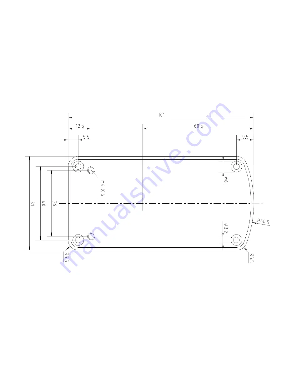
The GyroSet Link enclosure has two M4 sized screw threads on the back of the device 

that is designed specifically for mounting. As every vehicle and user is unique there 

is no general mounting bracket available.

Dimensions and position of mounting points

6

Summary of Contents for Gyroset Link

Page 1: ...emarks of Now Technologies Ltd registered in 18 Re ltanoda street Budapest 1053 Hungary European representative of the Manufacturer Now Technologies Ltd 18 Re ltanoda street Budapest 1053 Hungary www...

Page 2: ...2...

Page 3: ...s in life support and or safety applications is entirely at the buyer s risk and the buyer agrees to defend indemnify and hold harmless Now Technologies from any and all damages claims suits or expens...

Page 4: ...able WARRANTY Now Technologies Ltd provides one year s full warranty on the products This warran ty covers any defects in materials or workmanship with the exceptions stated below Faults resulting fro...

Page 5: ...ystem Before proceeding please make sure that one of the compatible devices are already installed on the chair and working properly For more information on how to set up the Omni please follow the ins...

Page 6: ...ure has two M4 sized screw threads on the back of the device that is designed specifically for mounting As every vehicle and user is unique there is no general mounting bracket available Dimensions an...

Page 7: ...nto the connector When there is no intention to use the wired interface please leave the connector s silicon cap in place Placement shall avoid the closeness of any magnetic materials or large iron pa...

Page 8: ...r the headset data cable must be accessible to allow the caretaker to plug in or out the cable GyroSet Link should be placed as such that the Status LED logo is visible for at least the caretaker pref...

Page 9: ...hat would surpass the power limitation and prevent the system from operation For the above reason if the Omni is configured with programmable parameter Sleep 12V to cut the power on SID connectors whe...

Page 10: ...input device connected to the Omni is Port 1 as shown on the picture below In case of PGDT IOM there is only one INPUT port where the D type connector can be connected Connecting the GyroSet Link to...

Page 11: ...ble to the GyroSet Glory Please make sure that the wiring meets the following criteria The GyroSet Link must be properly connected to PGDT Omni or IOM Cable that connects to the wheelchair controller...

Page 12: ...come disconnected a screen will appear on the Omni with error code 0905 WARNING Always make sure that the chair is configured in a way that the chair s on off switch is available to the user according...

Page 13: ...es There are three methods of programming the Omni Details of the actual programmable parameters are given in the SK78813 Programming chapter Ensure the R net Control System s Drive Acceleration and D...

Page 14: ...PC programmer to configure Omni Port 1 SID has to be set to propor tional To use the Click sensor of the headset to activate menu functions on the Omni Port 1 User control has to be set to Menu and Re...

Page 15: ...set User control is set Drive Acceleration and Deceleration settings are at a comfortable and safe level GYROSET LINK CONFIGURATION In this document we presume that the user is already familiar with...

Page 16: ...IVING 1 Imagine that Your head will act like a regular joystick 2 Press the headset s mode button shortly against the headrest then return Your head into a neutral position and keep it there until the...

Page 17: ...g criteria are met before trying to drive the wheel chair with the GyroSet Link Understanding of the intended use of the headset by getting familiar with the GyroSet Glory Headset s User Manual The ad...

Page 18: ...f the Personal Area Network must be changed frequently The password must be chosen carefully it should contain lower and upper case letters symbols and numbers The password must be minimum 8 ideally 1...

Page 19: ...When fifth button function is programmed so that the User can control actuators the headset will control If the GyroSet Link is mounted to a part that stays in level when the backrest is tilting it wo...

Page 20: ...ir If the Users head reaches the end of the range of operation the sweep of the head joystick is at maximum If the Users head reaches the safety zone the chair will stop If the Users head is in the ra...

Page 21: ...et Blue Breathing fade in fade out Connection to the headset established through RADIO and IDLE Blue Blinking Connection to the headset established through RADIO and ACTIVE Green Breathing fade in fad...

Page 22: ...System halted Software update Currently there is no possibility for the end user nor the distributor to update the firmware To update the software on the Gyroset Link the device has to be disassem ble...

Page 23: ...tects human health and the environment EXPOSURE TO RADIO FREQUENCY The GyroSet Glory has been tested and meets applicable limits for radio frequency RF exposure Specific Absorption Rate SAR refers to...

Page 24: ...h hu ROHS DECLARATION OF CONFORMITY We hereby declare that our products are compliant to RoHS Directive 2011 65 EU of the European Parliament and the Council from 08 06 2011 on restriction of the use...

Reviews: