NOVUS AUTOMATION
www.fieldlogger.net
74/104
COUNTINGS
From firmware version 1.10 on, it is possible to perform pulse counting at the digital inputs of the
FieldLogger
. Counting
resolution is 32-bit, which means that each input can count from “0” up to (2
32
– 1 =) “4294967295”. When reaching the
maximum value, next counted pulse will cause a roll-over and will reset the counting to zero.
The counting values can be accessed from Modbus registers (see the “FieldLogger – Modbus” document) and can also
be copied to a virtual channel, where they can be logged to memory or used by the alarms, for example. When applying
a new configuration in the digital channels, the counting’s of all of the digital channels are reset to zero.
Counting’s can be zeroed by writing it in the related Modbus registers.
Counting values are persistent, which means they will remain even when FieldLogger is turned off. Whenever it is turned
on again, countings are restarted from the values existent right before it was turned off.
OUTPUT RELAYS
FieldLogger
has two relay type outputs (
RL1
and
RL2
) which can act as
Alarms
or
Digital Outputs
.
When configured as Alarms, they act according to the configuration adopted for the alarms. When configured as Digital
Outputs, they are controlled remotely via Modbus commands (via RS485, USB or Ethernet).
RS485 INTERFACE
FieldLogger
RS485 interface can be enabled or disabled. When disabled, it does not impact the traffic that may exist on
the data bus. When enabled, it can be configured to operate as a Modbus RTU master or as a slave.
Slave
When operating as a Modbus RTU slave, the equipment makes the values of the channels available to be accessed
by the master of the Modbus network, either being a PLC, a SCADA application or any other device.
Master
When operating as a Modbus RTU master, it allows data from other devices on the bus to be read by
FieldLogger
and used in loggings, alarms, virtual channels or simply made available via another interface (Ethernet, for example).
Please, see the "Remote Channel" section for details of how to implement a Modbus RTU network with
FieldLogger
in the master role.
From firmware version 1.10 on, it can work as a gateway between a Modbus TCP network and a Modbus RTU
network. This way, all Modbus TCP requests received by
FieldLogger
with an identifier which is not “255” will be
forwarded to the Modbus RTU network, assuming that this request was addressed to a slave located in this network.
Modbus TCP requests received by
FieldLogger
with an identifier equals to “255” will be answered by the
FieldLogger
itself. This feature must be enabled in the Configurator software.
The RS485 interface can be configured to operate in the following speeds (baud rates): 1200, 2400, 4800, 9600, 19200,
38400, 57600 and 115200. Moreover, it can be configured to operate with one or two stop bits, and in the parities: even,
odd and none.
Further details about the implementation of a Modbus devices network via RS485 can be found in "RS485 & RS422
Basics”, available in the product CD.
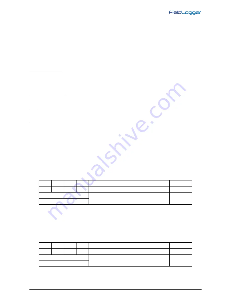
D1
D
D+
B
Bidirectional data line.
Terminal 50
D0
D
D-
A
Inverted bidirectional data line.
Terminal 49
C
Optional connection that improves communication
performance.
Terminal 48
GND
AUXILIARY RS485
FieldLogger
auxiliary RS485 interface is in the DB9 connector which is located under
FieldLogger
cover. Its main
function is to provide data to
FieldLogger
HMI, but from firmware version 1.20 on, it can be used as a generic interface,
acting as a Modbus-RTU slave. Some futher details can be seen in “HMI (Human-Machine Interface)” section.
As an interface to the HMI, it must be configured with baud rate 115200 bps, one stop bit and no parity.
As a generic interface, it can be configured to operate in the following baud rates: 1200, 2400, 4800, 9600, 19200,
38400, 57600 e 115200. Besides that, it can be configured to operate with one or two stop bits and with even, odd and
no parity.
D1
D
D+
B
Bidirectional data line.
Pin 4
D0
D
D-
A
Inverted bidirectional data line.
Pin 8
C
Optional connection that improves communication
performance.
Pin 7
GND


