


COMMUNICATING WITH THE SMART-MR15
To open a serial port to communicate with the receiver, complete
the following steps.
1. Launch
Connect
from the
Start
menu folder specified during
the installation process. The default location is
Start |
All Programs | NovAtel PC Software | NovAtel Connect
.
2. Select New from the Device Menu
.
3. Enter a name for the Connection setup.
4. Select
Serial
from the
Type
list.
5. Select the computer port to which the SMART-MR15 is
connected, from the
Port
list.
6. Set the COM port for the receiver to communicate through.
7. Select
115200
from the
Baud Rate
list.
8. Ensure the
Hardware Handshaking
box is not checked and
press
OK
.
9. From the
Device
menu select Open Connection.
10. Select the
Open
button to open SMART-MR15
communications.
Connect establishes the communication session with the
receiver and displays the progress. Once connected, the
progress box disappears and several windows open, includ-
ing the
Console
window. Connect is now ready for use to
view status information, enter commands or log data.
USING NOVATEL CONNECT
Connect
provides access to key information about your receiver
and its position. The information is displayed in windows
accessed from the
View
menu. For example, select
Position
Window
from the
View
menu to display the position solution of
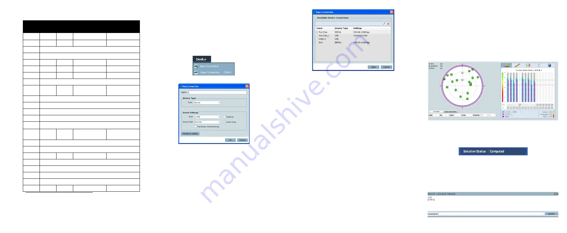
the receiver. To show details of the GNSS and geostationary
(SBAS) satellites being tracked, select the
Tracking Status
Window
from the
View
menu. Select
Help
from the main menu
for more details on Connect, its windows and features.
DETERMINING WHEN THE POSITION IS VALID
When the receiver has a valid position, the
Solution Status
field
in Connect’s
Position
window shows
Computed
:
ENTERING COMMANDS
The SMART-MR15 uses a comprehensive command interface.
Commands can be sent to the receiver using the
Console
window in Connect, which is opened from the
View
menu. Enter
commands in the text box at the bottom of the
Console
window.
Table 3: SMART-MR15 Streamlined Cable
TYCO
23-pin
COM1
COM2
TINNED LEAD
SIGNAL NAME
1
PWR+ (red)
PWR+
2
PWR- (black)
PWR-
3
RESERVED
4
RESERVED
5
2
AUXTX
6
3
AUXRX
7
2
TXD1
8
RESERVED
9
SIGGND2
(white/black)
SIGGND2
10
RESERVED
11
RESERVED
12
RESERVED
13
RESERVED
14
CHASSIS GROUND
a
a. Pin 14 of the TYCO 23-pin connector is connected to cable shields.
15
5
5
SIGGND1
(white/black)
SIGGND1
16
RESERVED
17
RESERVED
18
ER (blue)
ER
19
RESERVED
20
RESERVED
21
RESERVED
22
RESERVED
23
3
RXD1
SMARTAG


