background image

SMART-MR10 User Manual Rev 0B

59

Chapter 5

Bluetooth® Configuration

Bluetooth

 is a wireless radio communication standard designed for use over short ranges (within 

10 m). This chapter describes how to:

Enable 

Bluetooth

 on the SMART-MR10 receiver

Set up a PC/laptop with a 

Bluetooth

 adaptor

Locate a 

Bluetooth

-enabled SMART-MR10 in range

Communicate with the SMART-MR10 using 

Bluetooth

Stop communicating with the SMART-MR10 using 

Bluetooth

5.1

Enable Bluetooth on the SMART-MR10 Receiver

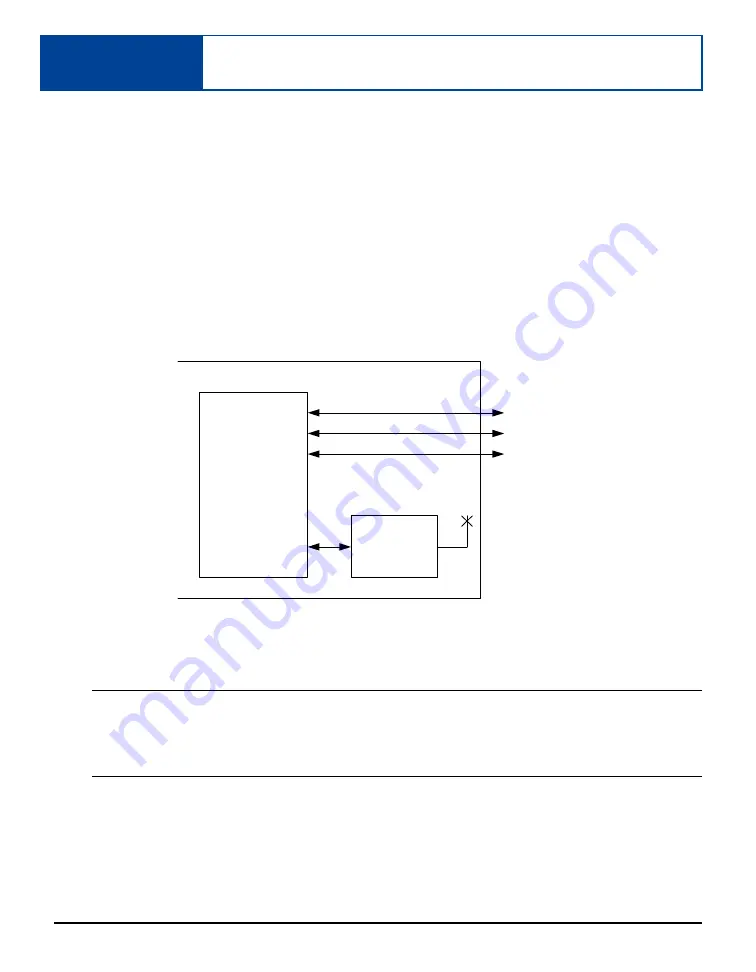
The SMART-MR10 

Bluetooth 

configuration is illustrated in 

Figure 18

:

 Figure 18: SMART-MR10 Bluetooth Configuration

Bluetooth

 is configured on the SMART-MR10 COM3 port and, by default, is enabled.

If the SMART-MR10 is turned off (or power is removed) then turned back on, the 

Bluetooth


mode is returned to the state it was in before power-down, as long as the SAVECONFIG 
command was issued before the unit was powered off. When you issue a FRESET command, 
COM3 defaults to 

Bluetooth

 mode.

If 

Bluetooth

 has been disabled, you will need to enable it before you can use it. From a PC/laptop, 

connect to a SMART-MR10 serial port. Open communication with the receiver using HyperTerminal 
or 

CDU

. Refer to 

Appendix B.2, BTCONTROL Enable/Disable Bluetooth 

starting on 

page 74

 fo

further information. Once your PC/laptop is configured for 

Bluetooth

 operation, you will be able to 

communicate with the SMART-MR10 through 

Bluetooth

.

SMART-MR10 

CPU

Bluetooth 

Module

DB9 Labeled COM1

DB9 Labeled COM2

COM1

COM2

AUX

COM3

DB9 Labeled AUX

SMART-MR10 Enclosure

Summary of Contents for SMART-MR10-GENERIC

Page 1: ...OM 20000130 Rev 0B SMART MR10 User Manual...

Page 2: ...thorized representative of NovAtel Inc The information contained within this manual is believed to be true and correct at the time of publication ALIGN GL1DE Narrow Correlator NovAtel OEMV and RT 20 a...

Page 3: ...ER 30 2 2 4 Controller Area Network CAN 30 3 Operation 32 3 1 Communications with the Receiver 32 3 1 1 Serial Port Default Settings 32 3 1 2 Communicating Using a Remote Terminal 33 3 1 3 Communicat...

Page 4: ...Using Bluetooth 61 5 5 Stop Communicating with SMART MR10 Using Bluetooth 63 A Technical Specifications 64 SMART MR10 Receiver Performance 64 SMART MR10 Specifications 65 B Commands 73 Syntax Conventi...

Page 5: ...MR10 Evaluation Cable Pinouts 69 8 SMART MR10 Streamlined Cable Pinouts 71 9 SMART MR10 Mating Connectors 72 10 Recommended Fuses 72 11 Commonly Used SMART MR10 Commands in Alphabetical Order 73 12 CO...

Page 6: ...and Line Arguments 52 11 Main Screen of WinLoad 55 12 WinLoad s Open Dialog 56 13 Open File in WinLoad 56 14 COM Port Setup 57 15 Searching for Card 57 16 Authorization Code Dialog 57 17 Upgrade Proce...

Page 7: ...Software No right is con veyed by this Agreement for the use directly indirectly by implication or otherwise by Licensee of the name of NovAtel or of any trade names or nomenclature used by NovAtel o...

Page 8: ...t it will be error free The Software is furnished AS IS and without warranty as to the performance or results you may obtain by using the Software The entire risk as to the results and performance of...

Page 9: ...sdiction of the courts of the Province of Alberta 10 Customer Support For Software UPDATES and UPGRADES and regular customer support contact the NovAtel GPS Hotline at 1 800 NOVATEL U S or Canada only...

Page 10: ...to Purchaser upon delivery to carrier Goods are provided solely for incorporation into the Purchaser s end product and shall not be onward delivered except as incorporated in the Purchaser s end prod...

Page 11: ...rating and maintenance procedures ii defects errors or nonconformities in the Products due to modifications alterations additions or changes not made in accordance with NovAtel s specifications or aut...

Page 12: ...RODUCTS OR USE IN OTHER THAN A NORMAL AND CUSTOMARY MANNER ENVIRONMENTAL CONDITIONS NOT CONFORMING TO NOVATEL S SPECIFICATIONS OR FAILURE TO FOLLOW PRESCRIBED INSTALLA TION OPERATING AND MAINTENANCE P...

Page 13: ...his equipment does cause harmful interference to radio or television reception which can be determined turning the equipment off and on the user is encouraged to try to correct the interference by one...

Page 14: ...supplier at the end of its life The objectives of the European Community s environment policy are in particular to preserve protect and improve the quality of the environment protect human health and...

Page 15: ...the WinLoad program to upgrade your OEMV receiver Contact Information Contact your local NovAtel dealer first for more information To locate a dealer in your area or if the problem is not resolved co...

Page 16: ...This manual describes the SMART MR10 specific commands and logs seeCommands starting on Page 73 and Logs starting on Page 91 Other supplementary manuals available on the accompanying CD and on our Web...

Page 17: ...re output as hexadecimal numbers and must be converted to binary format and in some cases then also to decimal For an example of this type of conversion please refer to the RANGE log in the OEMV Famil...

Page 18: ...Based Augmentation Systems including WAAS EGNOS and MSAS DGPS OmniSTAR VBS HP XP CDGPS NovAtel GL1DE RT 20 RT 2 and RT 2L For more information about the above refer to the NovAtel web site at http ww...

Page 19: ...Rugged water and dust tight enclosure consisting of a cast aluminum base and plastic radome Bluetooth Three 3 daylight viewable status LED indicators Range of installation options including a quick r...

Page 20: ...ASS RT 2 corrections and raw data code positions and DGPS OmniSTAR HP XP VBS CDGPS SBAS 20 Hz SMART MR10 L1L2 GPS RT 2 corrections and raw data code positions and DGPS OmniSTAR HP XP VBS CDGPS SBAS 20...

Page 21: ...for COM and power connections Use a serial COM connection to communicate with the receiver first A fused power supply user supplied or other user equipment 2 1 1 SMART MR10 Setup To connect and power...

Page 22: ...SIGGND1 4 CAN1 16 MKI 5 TXD2 17 PPS 6 RXD2 18 ER 7 TXD1 19 MODEa a The SMART MR10 is RS 232 RS 422 selectable through pin 19 MODE as shown in Table 3 8 RTS1 AUXTX 20 RESERVED 9 SIGGND2 21 RESERVED 10...

Page 23: ...lling the PC Utilities Once the SMART MR10 is connected to the PC laptop and a power supply install NovAtel s PC Utilities These include CDU a graphical user interface program 1 Start up the PC laptop...

Page 24: ...ecifications The SMART MR10 cable provides power in with a BATT label and power ground with a BATT label bare wires for connections from the SMART MR10 to a 12 to 24V vehicular power system or equival...

Page 25: ...mounting the SMART MR10 receiver Universal mounting plate NovAtel part number 70023085 shown in Figure 4 on page 25 Mounting plate with AG GPS 262 layout NovAtel part number 70023086 shown in Figure...

Page 26: ...26 SMART MR10 User Manual Rev 0B Chapter 2 Installation and Setup Figure 5 SMART MR10 AG GPS 262 Layout Mounting Plate 70023086...

Page 27: ...Installation and Setup Chapter2 SMART MR10 User Manual Rev 0B 27 Figure 6 SMART MR10 Pole Mount 70023087 All measurements are in millimetres unless specified otherwise INSERT...

Page 28: ...7 on page 69 for more information 2 2 Additional Features and Information This section contains information on additional features of the SMART MR10 which may affect the overall design of your receive...

Page 29: ...2b 3 710 3 002 2009 dec 30 11 20 58 db_userappauto smartag 0 1 100 2010 jan 25 17 32 44 userinfo no bt com1 If the yellow LED is flashing but does not progress to solid yellow within one minute then i...

Page 30: ...inus 0 5V minimum and logic low of 0 5V maximum with a rise and fall time of less than 1 ms Its output references signal GND and provides logic low output until its speed is greater than 1 km hr ER ca...

Page 31: ...and is entered and after a SAVECONFIG the CAN module is activated immediately on all subsequent start ups The module supports the following NMEA2000 Parameter Group Messages PGN PGN 129029 GNSSPositio...

Page 32: ...ates with your PC laptop or terminal via an RS 232 serial port For communication to occur both the receiver and the operator interface have to be configured properly The receiver s COM1 COM2 and AUX d...

Page 33: ...mmunications software package that emulates a terminal can be used to establish bidirectional communications with the receiver for example HyperTerminal or our own graphic user interface GUI program C...

Page 34: ...o data is transmitted from the COM ports except for the port prompt The console window displays a port name COM1 if connected to COM1 port or COM2 if connected to COM2 port Any of the above prompts in...

Page 35: ...nce of OK If a command is entered incorrectly the receiver responds with INVALID MESSAGE ID or a more detailed message WARNING Ensure the Control Panel s Power Settings on your PC laptop are not set t...

Page 36: ...for more information In most cases you need to provide a data link between the base station and rover station two NovAtel receivers in order to receive corrections The application of SBAS corrections...

Page 37: ...TCM V2 3 interfacemode com2 none rtcm off fix position 51 11358042 114 04358013 1059 4105 enter your own lat lon hgt log com2 rtcm3 ontime 10 log com2 rtcm22 ontime 10 1 log com2 rtcm1819 ontime 1 log...

Page 38: ...s CMR interfacemode com2 none cmr off fix position 51 11358042 114 04358013 1059 4105 enter your own lat lon hgt log com2 cmrobs ontime 1 log com2 cmrgloobs ontime 1 log com2 cmrref ontime 10 log com2...

Page 39: ...ize it is recommended that you use the standard form of RTCA RTCM RTCMV3 or CMR corrections as shown in the base and rover examples above This requires using the INTERFACEMODE command to dedicate one...

Page 40: ...describes the various message formats in more detail Information on how to send multiple commands and log requests using DOS or Windows can be found on our Web site at http www novatel com support kno...

Page 41: ...nt infrastructure and different GEOs EGNOS and ESTB broadcast two different signals The ESTB is broadcast on PRN pseudorandom number 126 and EGNOS is broadcast on PRNs 120 and 124 Due to the experimen...

Page 42: ...ormation on GL1DE Refer also to application note APN 038 Pseudorange Delta Phase PDP and GL1DE Filters at www novatel com support applicationnotes htm 3 5 ALIGN 3 5 1 ALIGN Heading Master and Remote C...

Page 43: ...result in noisier frequency output Refer to Appendix B 6 PDPFILTER Enable disable or reset the PDP filter starting on page 84 for more detailed information Once it is configured using the RADARCFG com...

Page 44: ...nly to select where you would like the applications installed on your PC It is strongly recommended that you close all applications before installing CDU and Convert You must close any applications th...

Page 45: ...ws the CDU windows from the View menu and their descriptions Most windows have a popup menu accessible by right clicking on the window with the mouse They provide a way to customize the window by chan...

Page 46: ...ick on a satellite to display information on that satellite When a valid position has been achieved dilution of precision DOP values can be viewed in the DOP window Open this window by selecting Const...

Page 47: ...irection dial is a compass that displays the direction of motion of the receiver over ground and its elevation both in degrees The white arrow indicates the elevation value on the vertical scale down...

Page 48: ...height HDOP Horizontal DOP Uncertainty of the two dimensional parameters latitude longitude VDOP Vertical DOP Uncertainty of the height TDOP Time DOP Uncertainty of the clock offset Console Window Thi...

Page 49: ...w select ASCII Messages Window from the View menu or select its button in the Window Toolbar Wizards Several wizards are available if you have the necessary receiver model to assist with various recei...

Page 50: ...reening particular logs out of large data files in either ASCII or Binary formats Figure 9 Convert4 Screen Examples 4 3 1 RINEX Format The Receiver Independent Exchange RINEX1 format is a broadly acce...

Page 51: ...vert4 sets this to zero t file type o for the observation and n for the navigation file Selecting the RINEX field see Figure 9 Convert4 Screen Examples on page 50 in the Convert4 To section causes the...

Page 52: ...ile is the same as the input file when converting to ASCII or binary formats The file extension however is altered to indicate the format of the data asc for ASCII bin for binary When converting to RI...

Page 53: ...nd with the issued auth code If you are upgrading to a higher firmware revision level you will need to transfer new program firmware to the OEMV family receiver using the WinLoad utility program As Wi...

Page 54: ...Transferring Firmware Files To proceed with your program upgrade you must first acquire the latest firmware revision You will need a file with a name such as OEMXXXX EXE where XXXX is the firmware rev...

Page 55: ...e file where XXXX program version level for example 1001 hex Using the WinLoad Utility WinLoad is a Windows based program used to download firmware to OEMV family cards The main screen is shown in Fig...

Page 56: ...selected your file the name should appear in the main display area and in the title bar see Figure 13 below Figure 13 Open File in WinLoad Communications Settings To set the communications port and ba...

Page 57: ...ed in main display area see Figure 13 Open File in WinLoad on page 56 4 Click on the Write Flash button to download the firmware 5 Power down and then power up the receiver when Searching for card app...

Page 58: ...58 SMART MR10 User Manual Rev 0B Chapter 4 PCUtilities Figure 17 Upgrade Process Complete 7 Close WinLoad This completes the procedure required to upgrade an OEMV family receiver...

Page 59: ...default is enabled If the SMART MR10 is turned off or power is removed then turned back on the Bluetooth mode is returned to the state it was in before power down as long as the SAVECONFIG command wa...

Page 60: ...the white Bluetooth icon If the Bluetooth icon is red as shown in Figure 21 the Bluetooth installation on your PC laptop is incorrect and you should return to step 1 Figure 21 Bluetooth Error Red 5 3...

Page 61: ...od window as shown in Figure 22 The PC laptop searches for available services If Bluetooth is working properly a COM port service appears 2 Double click the COM3 icon To use the serial COM port the SM...

Page 62: ...ecified in the Bluetooth configuration utility In the above example the terminal program must be configured to connect through COM21 5 Configure the port settings as follows 9600 bps no parity 8 data...

Page 63: ...Entire Bluetooth Neighborhood folder as shown in Figure 22 on page 61 3 Double click the SMART MR10 device icon in the Entire Bluetooth Neighborhood window The PC laptop searches for available service...

Page 64: ...rces Export licensing restricts operation to a maximum velocity of 515 metres per second Autonomous L1 1 5 m Autonomous L1 L2 1 2 m SBASa 0 6 m CDGPS 0 6 m DGPS 0 4 m OmniSTAR VBS 0 6 m XP 0 15 m HP 0...

Page 65: ...1898 Compliant Emulated Radar Output High Supply Voltage 0 5V Minimum Low 0 5 V Maximum Load 3K Ohm Minimum PPS Output 3 3 V CMOS Logic Compatible MKI Input 3 3 V CMOS Logic 5 V Tolerant Mode Pin 0 to...

Page 66: ...l Specifications a When tracking GPS satellites b See also the Notice section of this manual starting on Page 13 DIMENSIONS Notes 1 All dimensions are in millimetres 2 Mounting holes are labelled acco...

Page 67: ...Technical Specifications Appendix A SMART MR10 User Manual Rev 0B 67 Note All dimensions are in millimetres Antenna Phase Centre...

Page 68: ...f more than 36 V Two DB 9 connectors One of these is normally connected to a PC laptop serial RS 232 communication port and another to a modem or radio transmitter to propagate differential correction...

Page 69: ...TINNED LEAD SIGNAL NAME 1 PWR PWR 2 PWR PWR 3 CAN CAN 4 CAN CAN 5 2 TXD2 6 3 RXD2 7 2 TXD1 8 2 RTS1 AUXTX TXD3 9 SIGGND2 SIGGND2 10 RESERVED 11 RESERVED 12 RESERVED 13 RESERVED 14 CHASSIS GROUNDa a Pi...

Page 70: ...for 5A with an operating voltage of more than 36 V Two DB 9 connectors One of these is normally connected to a PC laptop serial RS 232 communication port and the other to a modem or radio transmitter...

Page 71: ...UB TINNED LEAD SIGNAL NAME 1 PWR PWR 2 PWR PWR 3 RESERVED 4 RESERVED 5 2 TXD2 6 3 RXD2 7 2 TXD1 8 RESERVED 9 SIGGND2 SIGGND2 10 RESERVED 11 RESERVED 12 RESERVED 13 RESERVED 14 CHASSIS GROUNDa a Pin 14...

Page 72: ...water sealed type produced by Tyco The following part numbers pertain to the mating connector required to make connections to the SMART MR10 These numbers are provided for information only and are not...

Page 73: ...ample you could type either RESET or reset 4 Except where noted either a space or a comma can separate commands and their required entries For example you could type either fix position 51 11358042 11...

Page 74: ...ge ID 8205 BTCONTROL switch Factory Default The Bluetooth module is enabled by default Example 1 to disable Bluetooth btcontrol disable Example 2 to enable Bluetooth btcontrol enable 1 If users want t...

Page 75: ...Family Firmware Reference Manual Baud rates higher than 115 200 bps are not supported by standard PC hardware Special PC hardware may be required for higher rates including 230400 bps 460800 bps and 9...

Page 76: ...a This table lists the commonly used SMART MR10 COM ports For a complete list of COM ports refer to the COM Serial Port Identifiers table in the COM command section of the OEMV Family Firmware Refere...

Page 77: ...bps baud 300 600 900 1200 2400 4800 9600 19200 38400 57600 115200 or 230400 Communication baud rate bps Bauds of 460800 and 921600 are also available on COM1 of OEMV 2 based products ULong 4 H 4 4 pa...

Page 78: ...nary Bytes Binary Offset 1 FRESET header This field contains the command name or the message header depending on whether the command is abbreviated ASCII ASCII or binary respectively H 0 2 target See...

Page 79: ...he receiver responds with an Insufficient Resources error Each COM port serial and USB already has RXSTATUSEVENT log associated with it This means that with 3 serial ports and no USB ports 7 logs are...

Page 80: ...meter is set so that logging is not disrupted by the UNLOGALL command To send a log only one time the trigger option can be ignored Abbreviated ASCII Example 2 log com1 bestpos once 0 000000 0 000000...

Page 81: ...ONCHANGED Output when the message is changed ONTIME Output on a time interval ONNEXT Output only the next message ONCE Output only the current message default ONMARK Output when a pulse is detected on...

Page 82: ...tual ports for USB port 1 USB2_ALL e 14 All virtual ports for USB port 2 USB3_ALL f 15 All virtual ports for USB port 3 AUX_ALL 10 16 All virtual ports for the AUX port b XCOM3_ALL 11 17 All virtual C...

Page 83: ...ort 1 virtual port 0 USB1_1 5a1 1441 USB port 1 virtual port 1 USB1_31 5bf 1471 USB port 1 virtual port 31 USB2 6a0 1696 USB port 2 virtual port 0 USB2_31 6bf 1727 USB port 2 virtual port 31 USB3 7a0...

Page 84: ...1DE filter works best with CDGPS or WAAS The PDP filter is smoother than a least squares fit but is still noisy in places The GL1DE filter produces a very smooth solution with consistent rather than a...

Page 85: ...reviated ASCII Syntax Message ID 970 pdpmode mode dynamics Factory Default pdpmode normal auto ASCII Example pdpmode relative dynamic Field Field Type ASCII Value Binary Value Description Binary Forma...

Page 86: ...e 4 Enum none H 3 freq_step Frequency step per kilometre per hour Range 26 11 28 12 or 36 11 default 36 11 8 Double Hz kph H 4 4 update_rate Specify how often to update radar output Range 1 2 5 10 20...

Page 87: ...isable 26 11 1 1 2 Example 2 to set the frequency step to 36 11 Hz kph update rate to 1 Hz and no smoothing radarcfg enable 36 11 1 1 2 Mode Description 2000 2000 ms The time period over which to smoo...

Page 88: ...field is used to set the number of seconds the receiver is to wait before resetting Abbreviated ASCII Syntax Message ID 18 reset delay Example reset 120 The RESET command can be used to erase any unsa...

Page 89: ...AUTO mode it does not track satellites from other systems This is because systems such as WAAS EGNOS and MSAS do not share broadcast information and have no way of knowing each other are there The tes...

Page 90: ...OEMV receivers work with SBAS systems including EGNOS Europe MSAS Japan and WAAS North America System Types ASCII Binary Description NONE 0 Don t use any SBAS satellites AUTO 1 Automatically determine...

Page 91: ...able NMEA standard logs is described in more detail in its own section of Chapter 3 of the OEMV Family Firmware Reference Manual The steps for configuring the receiver output through the command line...

Page 92: ...llows 1 In the Logging control window click Logging to one or more of the receiver s serial ports The Add Log window displays 2 Beside Select list select Complete List or NMEA List 3 Beside Log to fil...

Page 93: ...is log contains position and Emulated Radar ER signal information Message ID 8193 Log Type Asynch Recommended Input log radarsignala onchanged ASCII Example 1 stationary SMART MR10 RADARSIGNALA COM1 0...

Page 94: ...H 3 vel type Velocity type see Table 19 Position or Velocity Type on Page 95 Enum 4 H 4 4 speed Speed over ground m s Double 8 H 8 4 varf freq External VARF output frequency Hz Double 8 H 16 5 radar...

Page 95: ...eous Doppler 16 SINGLE Single point position 17 PSRDIFF Pseudorange differential solution 18 WAAS Solution calculated using corrections from an SBAS 19 PROPAGATED Propagated by a Kalman filter without...

Page 96: ...13 INTEGRITY_WARNING Large residuals make position unreliable 14 17 Reserved for SPAN capable receivers 18 PENDING When a FIX POSITION command is entered the receiver computes its own position and de...

Page 97: ...COM1 0 94 5 UNKNOWN 0 156 357 004c0001 3681 5010 3 GPSCARD N1GA DHC09401037 MCAGTP 1 00 22B 3 710 3 002 2009 Nov 30 11 08 19 DB_USERAPPAUTO SmartAg 0 1 100 2009 Nov 27 13 22 29 USERINFO LMX9830 0212...

Page 98: ...ww novatel com Part Description NovAtel Part SMART MR10 01018518 Full connectivity cable 23 pin socket to 3 DB 9 connectors twisted CAN I O pair and other bare wire connectors see SMART MR10 Evaluatio...

Page 99: ...rface 68 serial 32 streamlined 70 warranty 12 CAN See Controller Area Network CDU software 44 80 98 CMR 39 cold start 64 COM command 75 COM port 80 command CDU 34 communication 32 error message 35 exa...

Page 100: ...figuration note 39 corrections 35 68 70 operation 35 serial cable 68 70 directional communication 33 distance exceeded 96 dynamics 85 E echo 77 EGNOS 41 EGNOS European SBAS 90 e mail 15 Emulated Radar...

Page 101: ...n logs 92 O operation 32 optionality 17 outages 84 output connector 65 convention 17 log 79 81 status 33 34 syntax 73 overload 79 P parity 32 76 77 PC power settings 80 period 79 81 port Bluetooth 61...

Page 102: ...luetooth 59 SMART MR10 models 20 smooth 84 standby mode PC 80 static mode 85 status receiver 79 streamlined cable 70 support 12 15 syntax 73 T technical specifications 64 time 79 81 transmit 77 trigge...

Page 103: ...Index SMART MR10 User Manual Rev 0B 103...

Page 104: ...OM 20000130 Rev 0B 2010 05 12...

Reviews: