


H
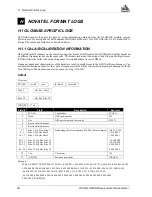
NovAtel Format Logs
GPS/GLONASS Receiver User Manual Rev 1
97
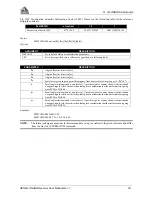
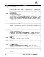
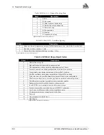
Receiver Status - Detailed Bit Descriptions of Self-Test (Table H.2)
Bit State
Description
Bit 0
0
1
Antenna
If the antenna connection is shorted together then this bit will be clear (0) indicating a possible antenna port problem.
This bit will be set good if the antenna is drawing the appropriate amount of current from the GPSCard antenna jack.
Overcurrent is tested not undercurrent.
Bit 1
0
1
Primary PLL
If a fault is detected in the Primary RF downconverter, this bit is set to 0.
When the Primary RF downconverter passes self-test, the bit will be set to 1.
Bit 2
0
1
RAM
If the bit has been set to 0, then RAM test has failed; please contact NovAtel Customer Service.
When this bit is set to 1, the receiver RAM has passed the self-test requirements.
Bit 3
0
1
ROM (Note: “ROM” includes all forms of non-volatile memory (NVM))
A zero bit indicates the receiver has failed the ROM test.
When this bit is set to 1, the receiver ROM test has passed the self test requirements.
Bit 4
0
1
DSP
If this bit is set to 0, one or both of the DSP chips has failed self-test; please contact NovAtel Customer Service.
This bit will be set to 1 when the digital signal processors (DSP) have passed the self-test requirements.
Bit 5
0
1
Primary AGC
This bit will be set clear if the Primary AGC is operating out of normal range. Failure of this test could be the result of
various possibilities, such as: bad antenna LNA, excessive loss in the antenna cable, faulty RF downconverter, or a
pulsating or high power jamming signal causing interference. If this bit is continuously set clear, and you cannot identify
an external cause for the failed test, please contact NovAtel Customer Service.
When set to 1, the Primary AGC circuits are operating within normal range of control.
Bit 6
0
1
COM1
If set to 0, the COM1 UART has failed self-test and cannot be used for reliable communications.
When set to 1, the COM1 UART has passed the self-test requirements.
Bit 7
0
1
COM2
If set to 0, the COM2 UART has failed self-test and cannot be used for reliable communications.
When set to 1, the COM2 UART has passed the self-test requirements.
Bits 8, 9, 10
0
1
Week / No Coarsetime / No Finetime
These bits indicate the state of the receiver time and are set only once, generally in the first few minutes of operation, in
the presence of adequate numbers of satellite signals to compute position and time.
If these bits are not all set to zero, then the observation data, pseudorange measurement, carrier phase, and Doppler
measurements may jump as the clock adjusts itself.
Bit 11
0
1
Primary Jammer Detection
Normal operation is indicated when this bit is 0.
If set to 1, the receiver has detected a high power signal causing interference. When this happens, the receiver goes into
a special anti-jamming mode where it re-maps the A/D decode values as well as special Primary AGC feedback control.
These adjustments help to minimize the loss that will occur in the presence of a jamming signal. You should monitor this
bit, and if set to 1, do your best to remedy the cause of the jamming signal. Nearby transmitters or other electronic
equipment could be the cause of interference; you may find it necessary to relocate your antenna position if the problem
persists.