


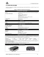


F
PowerPak II Enclosure
76
GPS/GLONASS Receiver User Manual Rev 1
F.3 HARDWARE CONFIGURATION
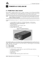
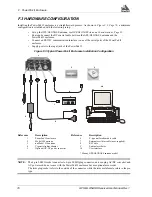
Installing the PowerPak II enclosure is a straightforward process. As shown in Figure F.3, Page 76, a minimum
configuration is established with the following setup:
•
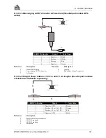
Set up the GPS/GLONASS antenna, see GPS/GLONASS Antenna Considerations, Page 23.
•
Route and connect the RF coaxial cable between the GPS/GLONASS antenna and the
PowerPak II enclosure.
•
Connect an RS232C communication interface to one of the serial ports of the PowerPak II
enclosure.
•
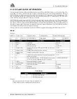
Supply power to the input jack of the PowerPak II.
Figure F.3 Typical PowerPak II Enclosure Installation Configuration
Reference
Description
Reference
Description
1
PowerPak II enclosure
6
Y-type null-modem data cable
2
Model 504 antenna
7
External oscillator cable (user-supplied)
3
or Model 514 antenna
8
RF Cable
4
Cigarette lighter adaptor
9
External oscillator
5
Optional AC-DC power converter
10
User interface
* Or any GPS/GLONASS antenna model
NOTE:
The 4-pin LEMO socket connector to 4-pin LEMO plug connector, auto-ranging AC/DC converter and
AC power cord do not come with the PowerPak II enclosure but are optional accessories.
The term plug/socket refers to the outside of the connector while the term male/female refers to the pin
type.
1
2
3
4
5
6
7
8
9
10