background image

~ 17 ~ 

NOVATEK-ELECTRO                                                                                                                UBZ-305 

  for improper phase sequence; 

  for decreasing of mains frequency lower that setting; 

  for increasing of mains frequency higher that setting; 

  for minimum insulation resistance of the motor winding; 

  for the motor phase loss (protection is operated when the motor current is disabled in one (two) phase). 

2.4.2

 Maximum phase current protection is of three-phase type.  

Maximum  current  protection  on  phase  is  three  phase.  It  is  enabled  when  one,  two  or  three  current  values 

reach the actuation set-point. 

The protection has time delay. The time delay can be definite (constant) or dependent (inverse-definite - 

SIT

very inverse-definite - 

VIT

 or 

LTI

; extremely inverse-definite - 

EIT

; ultra inverse-definite - 

UIT

, time delay of 

RI


type) - curves are shown in Appendix 

А. 

 
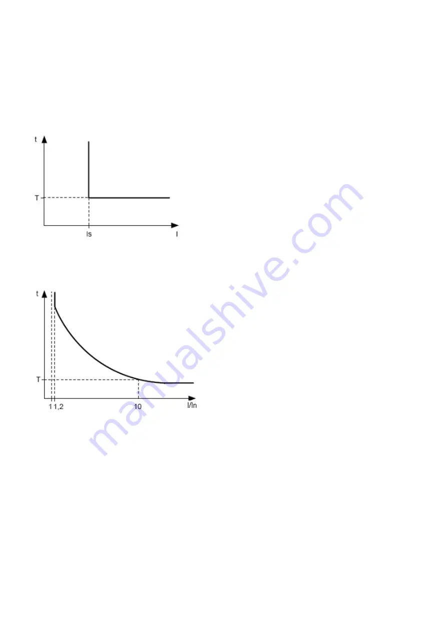
In  case  of  the  protection  with  definite  time  delay  the  motor  is  off 
when the current of one phase is more than specified for the time 
T (“Imax delay” parameter). 


Is  =  “Imax  coef”  (tripping  ratio);  *  “Rated  Inom”  (motor 

rated current), and T is the delay time of the protection operation 
(“Imax delay“).   
 

Example:  When 

“Imax  coef“  =  4.0,  “Rated  Inom”  =  10, 

“Imax delay“ = 10.0,  the motor will switch off in 10 seconds after 
one of the phase currents exceeds 40 amp. 


Fig.2.2


– Principle of protection with definite time delay 


Protection with dependent time delay corresponds to the standards IEC 60255-3 and BS 142. 


In corresponds to the set-point 

“Rated Inom” (motor 

rated current); 


T  (“Imax  delay”  parameter  is  time  constant  of  the 

protection  operation)  corresponds  to  time  delay  of  tripping 
for 10*In. 
 

For  very  large  currents  the  protection  has  a  feature 

with definite time delay: 


Fig.2.3


– Principle of protection with dependent time delay  


Appendix 

А provides curves for the time constant of the protection to equal 1 second (“Imax delay” parameter). 

When  setting  the  different  value  of  the  time  constant,  the  response  time  of  the  protection  is  changed 
proportional to the time constant (for example, when “Imax delay” = 10 seconds, operating time of protection at 
the same ratio of currents will increase 10 times). 


2.4.3

 Ground fault protection:  

  It is enabled when ground-fault current reaches the tripping threshold 

(“I earth tresh” parameter); 

  the  motor  switches  off  if  the  ground-fault  current  is  more  than  specified  for  the  time  T 

(“I  earth  delay” 

parameter). 

2.4.4

 Negative-sequence current protection (imbalance)  

Negative-sequence current protection (imbalance)  is enabled when a component of the negative sequence 

is more than the set-poi

nt (“I2 rev tresh” parameter) and stops the motor when time of this excess is more than 

specified value (“I2 rev delay” parameter”). 

If  the  analysis  of  tripping  cause  is  enabled 

(“A-s  I2  prot”=”On”),  then  in  case  of  protection  tripping  due  to 

exceeding  of  negative  sequence  current  not  because  of  line  voltages  imbalance  (in  this  case  the  motor 
problems are assumed), ARS after tripping will not occur (regardless of the value of “I2 rev protec” parameter). 

The coefficient of negative voltage (current) sequence is characteristic of unbalance of three-phase voltage 

(current). Approximately the coefficient of negative voltage sequence is determined by the formula:  


Summary of Contents for UBZ-305

Page 1: ...ctronics UNIVERSAL MOTOR PROTECTION UNIT UBZ 305 OPERATION MANUAL TECHNICAL PASSPORT The quality management system of production complies with the requirements of DSTU ISO 9001 2009 ISO 9001 2008 No U...

Page 2: ...ection for motor phase s break loss 20 2 4 15 Serviceability check of external magnetic starter 20 2 5 Selection of current transformers 20 3 UBZ DESIGN 21 4 SAFETY PRECAUTIONS 21 5 INTENDED USE 21 5...

Page 3: ...ons logbook 37 5 8 Motor control on UBZ front panel 37 5 9 Motor control using analog inputs 38 6 COMPONENTS 38 7 MAINTENANCE 38 8 TRANSPORTATION AND STORAGE 38 9 SERVICE LIFE SHELF LIFE AND MANUFACTU...

Page 4: ...ettings it is used in phrases as MNS mode or MNS list I t Rated current of CT it is set when external CTs using e g if C is of 0 66 300 5 type then I t equals to 300A In Rated current of the motor As...

Page 5: ...304 305 Control Panel program is designed to monitor the status and collect data of the UBZ 305 unit via RS 232 or RS 485 communication interfaces MODBUS Protocol The program allows for saving loadin...

Page 6: ...it flashes when the motor is in conditions of over current or thermal overload but relay off time has not come yet 6 Blue LED is on when data exchange with PC occurs 7 Connector for UBZ to a PC via R...

Page 7: ...type or similar input to connect differential current transformer zero sequence transformer input to measure current of 0 20 mA input to measure voltage of 0 10 V Main outputs load relay two groups o...

Page 8: ...Measured and Calculated Parameters Measurement functions Range Accu racy Mnemonic Address Data transfer units Currents Effective values of phase currents A 0 5 6300 2 Phase i1 Phase i2 Phase i3 30 31...

Page 9: ...Cos C 68 Temperature of transmitter 15 C minus 40 80 1 C Temp dat 1 69 5000 transmitter is off 1000 10 s c of transmitter 2000 10 transmitter breakout Temperature of transmitter 25 C minus 40 220 1 C...

Page 10: ...t relative to rated motor current it is used at Type Imax indep 155 Current protection delay tripping s Imax delay 0 3 600 10 0 156 Permit for protection operation Imax protec 0 2 2 0 Off protection i...

Page 11: ...current protection in of installed rated one 170 Tripping delay s Imin delay 1 100 5 171 Permit for protection operation Imin protec 0 2 2 0 Off protection is off 1 OnnAR protection is on ARS after tr...

Page 12: ...187 Permit for protection operation Phase Loss Prot 0 2 1 0 Off protection is off 1 OnnAR protection is on ARS after tripping is disable 2 On AR protection is on ARS is enabled 188 Frequency protectio...

Page 13: ...after ARS time 2 OffSt remote control is enabled motor start after UBZ energizing is disabled until the command for remote energizing 200 Temperature control Permit for temperature control and type of...

Page 14: ...otor motor insulation resistance Insulation mains frequency Frequency 212 Parameter display mode Indicat mode 0 1 0 0 Conti the parameter value is displayed continuously 1 15s the parameter value is d...

Page 15: ...nnection 3 StpnA warning and motor stop with ARS disabled after restoring the connection 224 Detection of response overtime s Overexce eding 0 120 0 0 It is disabled 225 Permit of UBZ communication vi...

Page 16: ...it is off when the voltage is less than the lower threshold 239 Entry in faults logbook Input U log 0 1 0 0 OffWr motor cutoff is considered the fault but not recorded in the fault logbook 1 OnWr moto...

Page 17: ...ant of the protection operation corresponds to time delay of tripping for 10 In For very large currents the protection has a feature with definite time delay Fig 2 3 Principle of protection with depen...

Page 18: ...2 4 5 Minimum phase current protection it is enabled when the currents of all three phases drops lower than the set point Imin tresh parameter and stops the motor when this drop time is more than the...

Page 19: ...the motor is stopped After the load relay disabling owing to thermal overload with ARS permitted the relay will be enabled again after the time more than the maximum of the two values time of thermal...

Page 20: ...e specified by Uimbal delay parameter 2 4 10 Phase sequence protection Correct phase parameter is enabled in case of improper phase sequence it disables the motor and blocks its further operation 2 4...

Page 21: ...THE UNIT INDEPENDENTLY TO OPERATE THE UNIT WITH MECHANICAL DAMAGES OF THE HOUSING TO PENETRATE MOISTURE ON CONTACTS OF TERMINAL BLOCKS AND THE INTERNAL ELEMENTS OF THE UNIT 5 INTENDED USE 5 1 SAFETY...

Page 22: ...ccordance with Fig 5 12 3 Programs developed by the user are allowed to be used for operation with UBZ 5 2 6 In case of MODBUS usage connect the communication lines to terminals 10 GND 11 line B RS 48...

Page 23: ...t breaker at a maximum current of 6 3 A T1 T3 Current transformer output 5 A T4 Differential transformer Fig 5 2 UBZ Connection Diagram 5 3 UBZ Control 5 3 1 Modes of UBZ control and status UBZ has fi...

Page 24: ...fter which ARS is disabled 3 AR 350 15 30 17 in case if the fault occurred and ARS is possible ARS time account is on 350 s left to ARS In the second and third variant information of the fourth line o...

Page 25: ...transfer to the MNS mode after reset to factory settings it 5 3 7 5 3 5 Mode of User level When UBZ unit is in the user level mode led MMSP is off To view and change the parameters of user level you s...

Page 26: ...it is required the following using DOWN and UP buttons select the parameter Fig 5 9 enter the menu where setting is changed by pressing SETUP button press both buttons SETUP and DOWN In case of restri...

Page 27: ...of UBZ it is assumed that this protection is enabled and all the required sensors are connected 5 4 1 UBZ operation before load relay on 5 4 1 1 UBZ operation after energizing first start up After ene...

Page 28: ...he indicator can display phase currents of motor or group of three two parameters selected by the user Table 2 5 The group of parameters selected by the user can be displayed constantly Indicat mode C...

Page 29: ...ed Off enabled On factory setting is Off number of stop bits parameter Stop bit 1 or 2 factory setting is 2 ATTENTION CHANGES OF THE COMMUNICATION SETTINGS EXCEPT THE UNIT ADDRESS WILL BE EFFECTIVE ON...

Page 30: ...ission data and control of data is based on the Table 5 3 5 5 4 2 Command for reading the register group Command code 0x03 reading n words For example reading of continuous 2 words from starting addre...

Page 31: ...low 0x89 CRC CHK low 0x89 CRC CHK high 0x56 CRC CHK high 0x56 5 5 4 4 Command for diagnostics Command code 08h diagnostics The 08h function provides a number of tests for checking the communication sy...

Page 32: ...ments Unsigned char data a pointer to the message buffer Unsigned char length the quantity of bytes in the message buffer The function returns the CRC value as a type of unsigned integer Unsigned int...

Page 33: ...ult code as per Table 5 12 Parameter value N 1000 N 1 5 1 Parameter value as per Table 5 12 Fault time N 1000 N 1 5 2 Low byte seconds high byte minutes 1000 N 1 5 3 Low byte hours high byte day of mo...

Page 34: ...n in remote control mode is determined by parameter MotorOp RS 2 5 When MotorOp RS 2 5 equal to Off 0 remote control of the motor is disabled With activated remote control parameter MotorOp RS 2 5 equ...

Page 35: ...mand UBZ RESTART is fulfilled after record of command code 88 in the command register Table 5 11 via RS 232 RS 485 interface After receiving Command UBZ RESTART UBZ does not return confirmation of rec...

Page 36: ...rent 100 303 3 901 3 Negative sequence current I2 rev Negative sequence current 304 4 901 4 Minimum phase current I min 305 5 901 5 Delayed start LongStart Current 306 6 901 6 Rotor blocking Block Rot...

Page 37: ...n its memory the code of the fault the value of the parameter on which the fault occurred and time of occurrence Note The fault time is determined by internal clock of UBZ Number of simultaneously sto...

Page 38: ...with PC via RS 232 type 01 1 Temperature transmitter types Pt100 Ni100 Ni120 It is delivered upon agreement with the Customer 7 MAINTENANCE 7 1 SAFETY PRECAUTIONS TO ENSURE SAFE OPERATION OF THE UNIT...

Page 39: ...uirements of current technical documentation and is fit for service Seal Head of QCD ___________________ Date of manufacture _____________ 11 CLAIMS DATA ______________________________________________...

Page 40: ...40 UBZ 305 NOVATEK ELECTRO Appendix CURRENT PROTECTION WITH DEPENDENT TIME DELAY mandatory...

Page 41: ...41 NOVATEK ELECTRO UBZ 305...

Page 42: ...or control via RS 232 RS 485 interface It is strictly forbidden to shutdown the motor by external machine the starter without UBZ de energizing As an exception it is allowed after the motor is switche...

Reviews: