- 6 -
REV-201М
NOVATEK-ELECTRO
1.2.3.3
“
Intermittent 1”
operation mode
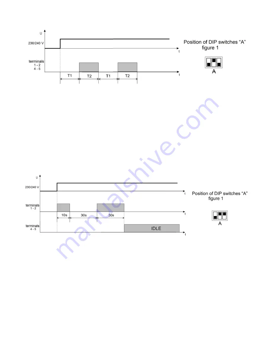
In the figure 4 there is represented the working algorithm of relay "
Intermittent 1
”.
Figure 4
– The working algorithm of relay “
Intermittent 1”
Time counting on each channel starts from the moment of power supply to
the terminals «
L1-N
» (Channel 1);
«
L2-N
» (Channel 2). Each channel has two adjustments
T1
and
T2
.
When the power supply is given to channel then the time reading
T1
starts, adjusted by the knobs of
potentiometers 3, 12 (figure 1) for the 1-st and the 2-nd channels correspondently
– time of pause. at this moment
GREEN LED indicator glows and the power load is turned OFF.
After the termination of this time interval (
T1
) power load turns ON and starts the timing countdown of another
interval (
T2
) that is adjusted by lower potentiometer knob 5, 10 (figure 1), for the 1-st and the 2-nd channels
correspondently
– time of work and this is indicated with the RED LED indicator.
After the termination of the
T2
timing countdown REV-201M turns OFF the power load and the LED indicator
changes to GREEN. From this moment new countdown basing the
T1
timing starts and the process keep on
working in cycle mode in this way further.
Note
– if the time interval of potentiometer
Т2
is equal to zero, the load relay will not switch over.
1.3.3.4
Control (pre-starting signalization
)
operation function
Figure 5
– The working algorithm of relay Control (pre-starting signalization)
ATTENTION! For the proper operation of REV-201M it should be connected in accordance with the
parallel channels operation
– Mode 2 (for details kindly see paragraph 1.1. Application).
After the power supply is given to the input terminals REV-201M turns
ON
the power load for the Channel 1
–
simultaneously
RED
LED (
Channel 1
) and
GREEN
LED (
Channel 2
) indicator starts glowing
– this indicates about
the preliminary signalization with the fixed time delay of 10 seconds.
After this interval the output relay of the “Channel 1” turns
OFF
for the fixed time of 30 seconds
– this is
indicated by
GREEN
LED glowing on the “Channel 1”.
After the expiration of the pause for the “Channel 1”
GREEN
LED change the color to
RED
– second
announcement signal with the time of 30 seconds;
After the end of the se
cond announcement signal the output relay of the “Channel” 1 turns
OFF
, LED changes
from
RED
to
GREEN
and the output relay of the “Channel 2” turns
ON
. At the same time
GREEN
LED of the
“Channel 2” change the color to
RED
and switches to
IDLE
state.
If you want to restart the algorithm
– you will have to turn
OFF
the power supply and turn it
ON
afterwards.


