background image

  MX40 Pro LED Display Controller User Manual 


www.novastar.tech 


  19 


Device Management 

7.1 

Set a Backup Device 

Specify a backup device for the current device so that the backup device can take over the master device when it 
fails. 

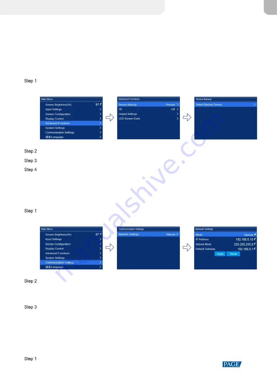
  On the main menu screen, choose 

Advanced Functions

 > 

Device Backup

Figure 7-1 Device backup 


  Choose 

Select Backup Device

  Select a device from the devices found. 

  Select 

Yes

 in the displayed dialog box. 

A prompt will be displayed after the operation is successful. 

7.2 

Set an IP Address 

Manually set a static IP address for the device or set up the device to automatically obtain an IP address. 

  On the main menu screen, choose 

Communication Settings

 > 

Network Settings

Figure 7-2 Network settings 


  Choose 

Mode

 and then select a mode from the drop-down options. 


Manual: Manually set a static IP address for the device. 


Auto: The device automatically obtains an IP address. 

  If the manual mode is selected, set an 

IP Address

Subnet Mask

 and 

Default Gateway

 and select 

Apply

. If the 

automatic mode is selected, this step is not required. 

If you want to reset the IP address to the default, select 

Reset

7.3 

Enable Mapping 

After the Mapping function is enabled, cabinets can display the controller number, Ethernet port number and 
receiving card number, allowing users to easily obtain the locations and connection topology of receiving cards. 

  On the main menu screen, choose 

Screen Configuration

 > 

Mapping

XI'AN 

NOVASTAR 

TECH 

CO., 

LTD.

Summary of Contents for MX40 Pro

Page 1: ...MX40 Pro LED Display Controller User Manual XI AN N O VASTAR TECH CO LTD ...

Page 2: ...er Manual www novastar tech i Change History Document Version Release Date Description V1 0_02 2021 09 25 Updated the application diagrams Updated the LCD home screen diagram V1 0_01 2021 09 01 First release XI AN N O VASTAR TECH CO LTD ...

Page 3: ...lution and Frame Rate HDMI1 HDMI2 and DP only 11 6 1 3 Adjust Color 12 6 1 4 Set HDR HDMI1 and HDMI2 only 13 6 1 5 Input Source Backup 13 6 2 Set Internal Input Sources 14 6 3 Set Output Parameters 15 6 3 1 Adjust Screen Brightness 15 6 3 2 Adjust Gamma and Color Temperature 15 6 3 3 Enable 3D Function 16 6 3 4 Set Low Latency 16 6 3 5 Set Bit Depth 17 6 3 6 Set Sync Source 17 7 Device Management ...

Page 4: ...rol Innovative hardware architecture design to make wiring easy and flexible Cascaded devices are controlled via Ethernet and operation commands can be received as soon as they are sent High bit depth inputs do not reduce the loading capacity by half and blank configurations do not occupy any capacity using the Ethernet port bandwidth to the full potential Not only a controller but also a processo...

Page 5: ...nus and messages Knob On the home screen press the knob to enter the main menu screen On the main menu screen rotate the knob to select a menu item or adjust the parameter value Press the knob to confirm the operation Hold down the knob and BACK buttons simultaneously for 5s or longer to lock or unlock the buttons BACK Exit the current menu or cancel the operation 2 2 Rear Panel Inputs INPUT area ...

Page 6: ... 1 2 1 Maximum resolution 4096 2160 60Hz 8192 1080 60Hz Forced Minimum resolution 800 600 60Hz Support custom input resolutions Maximum width 8192 8192 1080 60Hz Maximum height 8192 1080 8192 60Hz Support common standard resolutions up to 3840 2160 60Hz Supported frame rates 23 98 24 25 29 97 30 47 95 48 50 59 94 60 71 93 72 75 100 119 88 120 143 86 1 44 150 179 82 180 191 81 192 200 215 78 216 23...

Page 7: ...I LOOP 1 An SDI loop output connector SPDIF OUT 1 A digital audio output connector Reserved Control CONTROL area Connector Qty Description ETHERNET 2 2x Ethernet control ports They can be connected to the control PC or used for device cascading control GENLOCK 1 A pair of Genlock signal connectors Support Bi Level Tri Level and Black burst IN Accept the sync signal LOOP Loop the sync signal For st...

Page 8: ...0 Pro has two typical application scenarios as shown below In those application examples the LED screen size is 4096 2160 and the fiber converter used is NovaStar s CVT10 Application 1 Synchronous Mosaic Application 2 Long Distance Transmission via OPT Ports XI AN N O VASTAR TECH CO LTD ...

Page 9: ...The buttons will be locked only in the following situations Hold down the knob and BACK button simultaneously for 5s or longer Operate and control the device in VMP software The connection status of the Ethernet ports Blue Connected Gray Disconnected 192 168 0 10 The device IP address For related operations please refer to 7 2 Set an IP Address Input HDMI1 HDMI2 DP SDI Internal The device input so...

Page 10: ...nnected Bottom line Sync Active Input The sync signal currently used and the signal status Sync Active Input Sync with the frame rate of the current input source Sync Genlock Sync with the frame rate of the Genlock signal Sync Internal Sync with the frame rate of the internal clock of the device Color code Blue The signal is normal Red The signal is abnormal For the synchronization settings please...

Page 11: ...integral multiple of the number of cabinet rows or columns and it must be greater than or equal to the number of cabinets loaded by the last port 5 1 Quick Screen Configuration via Front Panel Screen 5 1 1 Set Input Source Select the desired input source and complete the related settings such as resolution and frame rate If the resolutions of the input source and screen are the same the image can ...

Page 12: ...in the root directory of the USB drive in advance Insert the USB drive into the USB connector on the device front panel On the main menu screen choose Screen Configuration Send Cabinet Config File Figure 5 2 Send cabinet config file Select the target configuration file Select Yes in the displayed dialog box After the configuration file is successfully sent a message appears on the menu screen and ...

Page 13: ...Front View Select the data flow for the cabinets loaded by Ethernet port 1 H Offset Set the horizontal offset of the displayed image V Offset Set the vertical offset of the displayed image 5 2 Free Screen Configuration via VMP The VMP software can be used to configure either the regular screens or complex screens and supports free wiring of the cabinets plus the ability of calculating the used loa...

Page 14: ...the video source you selected in the previous step Figure 6 2 Input source information View the input source information 6 1 2 Set Resolution and Frame Rate HDMI1 HDMI2 and DP only Set the resolution and frame rate of the input source If the resolutions of the input source and screen are the same the image can be displayed pixel to pixel A lower frame rate may result in image flickering while a hi...

Page 15: ... this parameter is not set manually the value that comes with the input source can be used On the main menu screen choose Input Settings input source EDID The input source is HDMI1 HDMI2 DP or SDI Figure 6 5 Infoframe override Set the following parameters as required Figure 6 6 Override parameters Select From Input and the device will read the attribute value that comes with the input source Press...

Page 16: ... the HDR format is SDR here no parameters need to be set HDR related parameters include PQ MaxCLL nits The peak screen brightness which will take effect only when PQ MaxCLL Override is set to Ambient Illuminance Lux The ambient light intensity Low Grayscale Compensation The compensation for the grayscale in low grayscale conditions allowing for more precise grayscale The HLG related parameters inc...

Page 17: ...oubleshooting On the main menu screen choose Input Settings Internal Source Figure 6 10 Internal source Select Image Select a static picture or a motion picture When the relevant parameters of the image are displayed set the parameters according to your actual needs otherwise please skip this step Press the BACK button to go back to the upper level menu and select Resolution Set Mode to Custom or ...

Page 18: ...rm Choose Screen Configuration Save to RV Card Figure 6 13 Save to RV card Select Yes in the displayed dialog box After the brightness value is successfully saved a message appears on the menu screen 6 3 2 Adjust Gamma and Color Temperature Adjust and save the Gamma and color temperature On the main menu screen choose Advanced Functions LED Screen Color Figure 6 14 LED screen color Adjust the Gamm...

Page 19: ...g to the format of the accessed video source Right Eye Start Set the start position of the right eye image When the video source format is SBS or TAB and the left and right eye images are provided this parameter can be set Eye Priority Set which image is sent first the right eye image or the left eye image Wear the 3D glasses to watch the display If the display is abnormal set the parameter value ...

Page 20: ...he knob to confirm 6 3 5 Set Bit Depth Set the output bit depth of the input source On the main menu screen choose Advanced Functions Output Settings Figure 6 18 Bit depth Select Bit Depth and then select the desired bit depth value from the drop down options If Auto is selected the output bit depth is the same as the input bit depth 6 3 6 Set Sync Source Select a synchronization signal for the di...

Page 21: ... rate of the Genlock signal Internal Sync with the frame rate of the controller s internal clock Press the BACK button to go back to the upper level menu Select Sync Shift Choose Adjustment Mode and then select the desired mode from the drop down options When you select Phase Angle or Percentage please set the corresponding value XI AN N O VASTAR TECH CO LTD ...

Page 22: ...On the main menu screen choose Communication Settings Network Settings Figure 7 2 Network settings Choose Mode and then select a mode from the drop down options Manual Manually set a static IP address for the device Auto The device automatically obtains an IP address If the manual mode is selected set an IP Address Subnet Mask and Default Gateway and select Apply If the automatic mode is selected ...

Page 23: ...ut screen always display the current frame The input source is played normally Blackout Make the output screen go black The input source is played normally 7 5 Diagnostics Perform device diagnostics then view and export the result On the main menu screen choose System Settings Diagnostics Figure 7 5 Diagnostics Select Yes in the displayed dialog box After successful diagnostics do any of the follo...

Page 24: ...ctory Settings Reset part or all of the device data to the factory settings On the main menu screen choose System Settings Factory Reset Figure 7 7 Factory reset Do any of the following according to the data you want to reset Reset part of the data Reset all the data except the imported files network parameters language settings and device name a Select Keep User Data b Select Yes in the displayed...

Page 25: ...tically after the specified amount of time if no action is performed during the time specified On the main menu screen choose System Settings Return to Home Figure 8 2 Session timeout value Select 30s 1min or 5min from the drop down options as required 8 3 View Service Information View the service information of NovaStar allowing users to ask questions and give feedback On the main menu screen cho...

Page 26: ...densing Physical Specifications Dimensions 482 6mm 94 2mm 467 0mm Packing Information Packing box 660 0 mm 570 0 mm 210 0 mm kraft paper box Accessory box 408 0mm 290 0mm 50 0mm white cardboard box Accessories 1x Power cord 1x Ethernet cable 1x HDMI cable 1x DP cable 1x Quick Start Guide IP Rating IP20 Please prevent the product from water intrusion and do not wet or wash the product The amount of...

Page 27: ...XI AN N O VASTAR TECH CO LTD ...

Reviews: