background image

NovaLynx Corporation 


200-WS-01 

Page 9 

April 2021 


2.


Spin the anemometer cup assembly. It should turn freely. Apply a few drops of light machine oil 
(e.g. fishing reel oil) to the bearing if needed. 

Note:


Do not use WD-40 or similar products, as they 

wear off quickly, leaving the bearing dry and susceptible to rust.


3.


Inspect the cable and ensure it is secured to the mast to prevent damage due to wind whipping.


4.


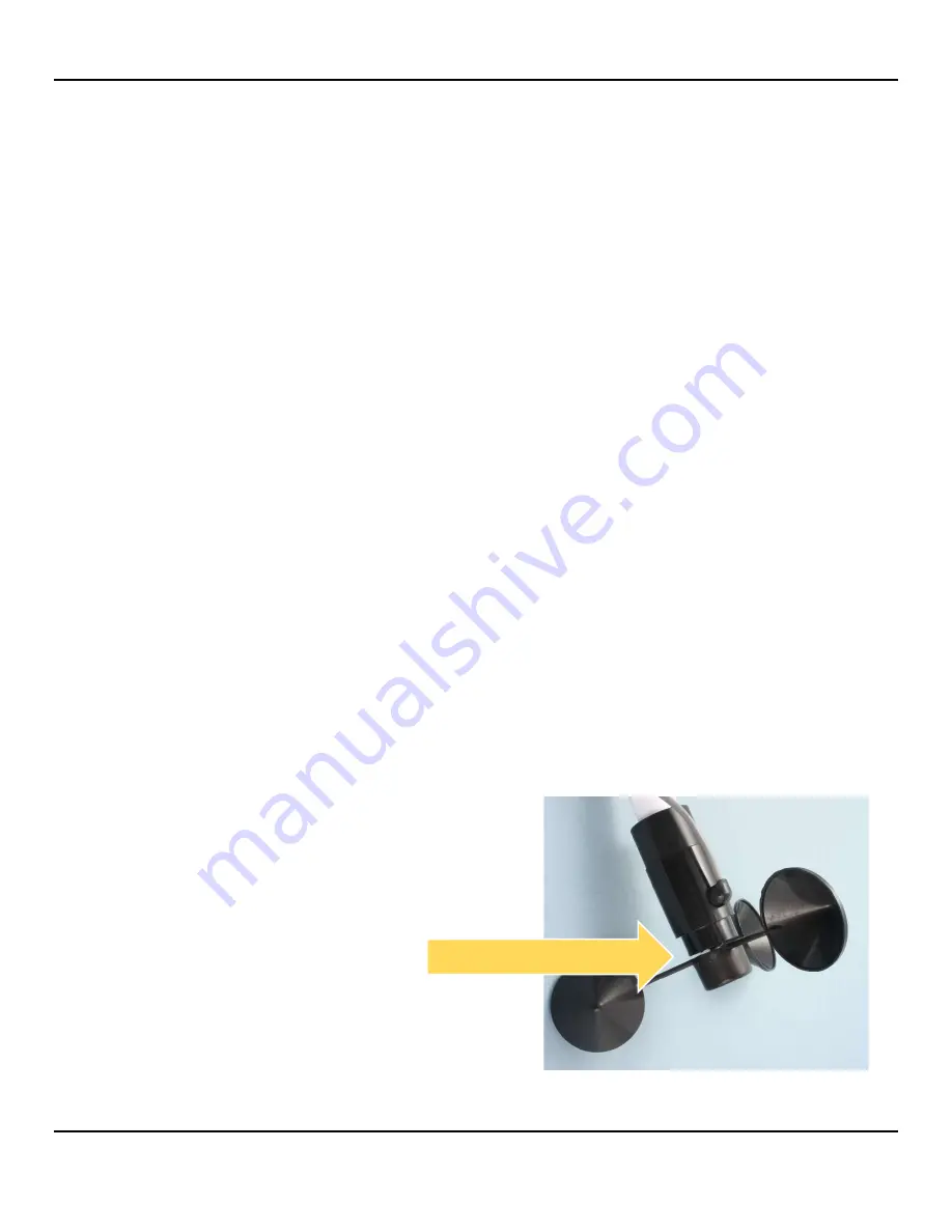
If one of the cup arms is damaged, the sensor may be user-repairable. Order the NovaLynx kit that 
matches your sensor: 

2502-14-01B


3-magnet wind cup assembly for 

wind speed

 sensors 

2502-14-01C


1-magnet wind cup assembly for 

wind run

 sensors 

10


FUNCTIONAL TESTS 


The following checks can be done with an ohm-meter after the sensor has been dismounted from the 
tower or tripod. These tests can help determine whether the sensor needs repair or adjustment. 
 
Set the ohm-meter to a low resistance range and touch its leads together to check for zero ohms. If it is 
an analog meter adjust the dial to read zero ohms. Connect the ohm-meter to the signal wires from the 
anemometer (polarity is not important). 

Rotate the cup assembly slowly until you notice the meter reading drop to less than 10 ohms. Continue 
to rotate until the switch opens. Do this for each of the magnets in the cup assembly (3 magnets in 
wind speed models, 1 magnet in wind run models).  


If the meter always reads a low resistance then the reed switch is not opening (the contacts 
may have welded together) or there may be a short circuit in the cable.  


If the switch never closes then there may be a break in the cable or the magnets are not near 
enough to activate the switch. Check the distance between the cup assembly and the base. The 
gap should be about 1/16" (1.6 mm). 


1/16" gap all sides 

Summary of Contents for 200-WS-01 Series

Page 1: ...DOC 200 WS 01 UM 20210413 200 WS 01x User Manual WeatherPort Wind Speed Sensors Wind Run Sensors Phone 530 823 7185 Email nova novalynx com Website www novalynx com...

Page 2: ...items If packing facilities are not available take the equipment to the nearest Post Office UPS or other freight service and obtain assistance with the packaging Please write the RA on the outside of...

Page 3: ...ARD 4 2 INTRODUCTION 4 3 PRECAUTIONS 4 4 SPECIFICATIONS 5 5 MODEL NUMBERS AND FEATURES 5 5 1 Wind Run Sensors 5 5 2 Wind Speed Sensors 6 6 SITE SELECTION 6 7 MOUNTING OPTIONS 7 8 INSTALLATION 8 9 MAIN...

Page 4: ...ached to the side of the sensor as shown in the photo or it exits the base Be aware that if the cable exits the base it must be threaded through the supporting mast Cable Side Exit The 200 WS 01 is a...

Page 5: ...12 m 2 conductor 24 AWG shielded tinned leads Except Model 200 WS 01C which has 1 0 3 m hookup wire 1 07 inch diameter by 0 82 inch socket 27 mm dia x 21 mm Note Standard 3 4 IPS pipe is 1 05 o d and...

Page 6: ...threshold due to a characteristic of the Teflon bearing 6 SITE SELECTION WARNING Avoid overhead power lines whenever possible If there are overhead power lines use extreme care to prevent contact wit...

Page 7: ...ious lengths Swaged mast segments can be fitted together to obtain the overall height needed The swaged end is the correct diameter for mounting 200 WS 01x sensors 1 07 1 25 SWAGED ALUMINUM MAST 3 75...

Page 8: ...ies that are resistant to ultra violet radiation and place them at two foot intervals Leave a drip loop of cable below the entry point to the equipment enclosure to help keep moisture out Turn off pow...

Page 9: ...ripod These tests can help determine whether the sensor needs repair or adjustment Set the ohm meter to a low resistance range and touch its leads together to check for zero ohms If it is an analog me...

Page 10: ...NovaLynx Corporation_____________________________________________________________________________________________________________________ 200 WS 01 Page 10 April 2021 APPENDIX A TRIPOD DIMENSIONS...

Reviews: