INERTIA-2464
Technical & Programming Manual
Page 11
Copyright (c) 1996,
INERTIA FIRE SYSTEMS
PLACING INTO OPERATION
Suitably qualified technicians must install the panel. The following check procedures are recommended after
every installation and prior to initial power-up.
A thorough visual inspection should be made to every aspect of the fire panel. This includes loose wire
strippings, metal filings, loose circuit boards, loose cabling, damage in transit etc.
All problems must be rectified immediately as they could cause incorrect operation or permanent damage to
the equipment.
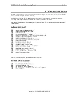
INITIAL CHECKLIST
System General Appearance Good
Cabinet Colour and Condition Good
Cabinet Keyed 003
All Circuit Boards Firmly Fastened
Manual Call Point Fitted & Functional (Australian version only)
Viewing Window Clear and Firmly Secured
Cable Entries Adequately Sealed
200/220/240VAC Cabling Correctly Terminated
All Earthing Secured
Transformer Securely Mounted
Transformer Correctly Wired
All Ribbon Cables Firmly Secured
All Operational Zones Adequately Identified
AC Fuse 2.5A Fitted And OK
Door Holder Fuse 3A Fitted and OK
All Other Components Securely Inserted
Auxilary and Mimic fuse 1A fitted and OK
Manufacturing Label Affixed
You are now ready to power up the 2464 fire indicator panel.
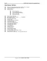
POWER UP CHECKLIST
Ensure Batteries Are Disconnected.
Turn Mains Switch to "ON"
The "Mains On" LED Should Light.
Allow 15 Seconds for the Panel To Perform Its Start Up Tests.
Connect Batteries
Summary of Contents for INERTIA-2464/64
Page 58: ......
Page 59: ...INERTIA 2464 Technical Programming Manual Page 1 Copyright c 1996 INERTIA FIRE SYSTEMS...
Page 60: ...Page 2 INERTIA 2464 Technical Programming Manual Copyright c 1996 INERTIA FIRE SYSTEMS...
Page 61: ...INERTIA 2464 Technical Programming Manual Page 3 Copyright c 1996 INERTIA FIRE SYSTEMS...


