background image

Northstar 

M121/M84 

 Installation and Operation Manual

88

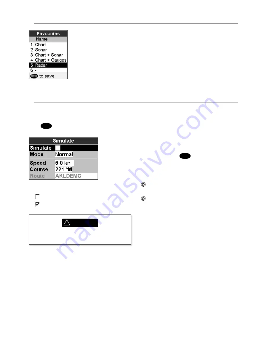
Simulate mode is a way of becoming familiar 
with the Instrument (see section 2-6).

Press 

MENU

 twice, then select 

Simulate

:

Simulate


 Turn simulate mode off


 Turn simulate mode on

19-15 Setup > Favorites

See section 2-7-2.

19-16 Setup  > Simulate 

The options required for Normal are:


Speed

: The simulated boat speed to use.


Course

: The simulated course over ground.

Note:

 To select the start point, go to the chart 

window before starting the simulation. Then:

•  To start the simulation from the boat 

position, press 

ESC

 to switch to centre on 

boat mode. 

•  To start the simulation from a different point, 

move the cursor to that point on the chart.

 Tip:

 To calculate a course, use the cursor (see 

section 3-2-1).

 Tip:

 As the boat moves, vary Course to 

simulate the boat moving off course.

2 Demo

Simulates a boat moving along a route and 
automatically displays different Instrument 
functions. The options required for Demo are:


Speed

: The simulated boat speed to use.


Route

: The route to follow.

Mode

There are two choices for 

Mode

:

1 Normal

Simulates the boat moving from the selected 
start point at the given speed and heading.

!

WARNING

Never have simulate mode on when the 
Instrument is navigating on the water.

Summary of Contents for M121

Page 1: ...www northstarnav com M121 M84 Multi Function Unit Installation and Operation Manual ...

Page 2: ...on to navigating 19 3 2 Chart window 21 3 3 Distance and bearing calculator 23 3 4 Projected course 24 3 5 Tracks and tracking 24 4Videowindow 25 5Navigation Highwaywindow 26 6Navigation Waypoints 26 6 1 Waypoints window 27 6 2 Managing waypoints 27 7Navigation Routes 29 7 1 Routes window 29 7 2 Managing routes 29 8Satellites 32 8 1 Satellite window 33 9Sonarfishfinding Introduction 33 9 1 Using t...

Page 3: ...s 51 13 7 Calibration 53 14Tideswindow 54 15Usercardwindow 55 16AIS 57 16 1 Viewing AIS Vessels 57 16 2 Dangerous Vessels 58 16 3 AIS Windows 58 17DSC Buddytrackwindows 60 17 1 The windows 60 17 2 Using the windows 61 18Radar 62 18 1 Radar window 62 18 2 Radar modes 63 18 3 Enabling the radar functionality 63 18 4 Selecting standby mode or transmit mode 63 18 5 Disabling the radar functionality 63...

Page 4: ... 91 20 3 Installation The display unit 92 20 4 Installation Power data cable 94 20 5 Installation GPS antenna 95 20 6 Installation Sonar transducer 96 20 7 Installation Northstar petrol gasoline sensors 96 20 8 Installation SmartCraft 97 20 9 Installation Radar 97 20 10 Installation Other NavBus instruments 98 20 11 Installation Other NMEA instruments 99 20 12 Installation Setup and test 99 Append...

Page 5: ...IS features on this chart plotter are designed as a safety aid only and do not guarantee safety at sea AIS transmission is mandatory on some but not all vessels You should check your local laws and regulations for requirements in your area As a result of different legal requirements different vessel sizes and uses you should not assume that your AIS equipped chart plotter will show the location of...

Page 6: ...8 1 Saving and loading data with a user card 15 User card Chart data Chart features built in world chart 3 2 Chart details 3 2 4 5 Chart card Tides at a port 14 Chart card AIS 16 Alarms Built in alarms 2 5 Boat data Data at top of main displays 2 7 3 Compass at top of main displays 2 7 4 Dedicated data display 12 Fuel Fuel computer Instrument petrol gasoline engine 13 Fuel sensors Fuel computer Sm...

Page 7: ...n the optional sensors and instruments that are installed The Video window requires the M121 M84 to receive video from a compatible source such as a camera Fuel functions require one or more petrol gasoline or diesel fuel sensors to be installed SmartCraft engine functions require a SmartCraft system to be installed For information on using SmartCraft see the SmartCraft Gateway Installation and Op...

Page 8: ...art window You can plug in up to two chart cards at once If the chart shows a region not covered by a chart card then it displays a simplified built in world chart 2 User cards store navigation data A user card allows navigation data to be transferred to another compatible instrument see section 15 Removing a plug in card Turn the M121 M84 off see section 2 2 Open the card cover on the right of the...

Page 9: ... turn each locking collar anticlockwise until you can pull the plug out 4 Store the M121 M84 in a dry clean place Replacing the display unit 1 Plug the connectors into the back of the display unit Match the connector s color to the socket color Insert each connector and turn the locking collar clockwise until it is finger tight Nothing will be damaged if a cable is plugged into the wrong socket by...

Page 10: ... y Cursor keys to move the cursor or the selection highlight u The key selects which window you are working with The Active window is indicated with a red border i The key allows you to quickly switch between your saved favorite displays o GOTO AUTO For a navigation display Start navigating to a point waypoint or along a route see section 3 1 2 For sonar display Select a sonar operating mode see s...

Page 11: ...lays for easy access from the key e MENU Show a menu of the options for the current active window The setup menu can be opened by pressing MENU twice r ENTER Start an action or accept a change t Changes the range on a window eg Chart or Sonar zooms y Cursor keys to move the cursor or the selection highlight u The key selects which window you are working with The Active window is indicated with a r...

Page 12: ...ve the highlight to the command for example Goto cursor then press ENTER Changing data First press or to move the highlight to the data to change then a To change a tick box means On or Yes means Off or No Press ENTER or to change the tick box b To select an option 1 Press ENTER to display the list of options 2 Press or to move the highlight to the option you want then press ENTER c To change a na...

Page 13: ... off You can now turn the Instrument off manually 2 3Backlightandnightmode To go to the Backlight window press briefly Backlight The display and keys are backlit To change the backlight level select Backlight then press to dim or to brighten When you have finished press ESC Tip Press twice to give the brightest screen with maximum backlight and Night mode off Nightmode Night mode sets the palette ...

Page 14: ... position as a waypoint called MOB 2 The Instrument changes to the chart window with the MOB waypoint at the centre of the chart The chart zooms in for accurate navigation If the chart can not show the required small scale the Instrument changes to plotter mode a white window with crosshatching and no chart details see section 19 2 3 The Instrument sets the MOB waypoint to be the destination to na...

Page 15: ...strument ignores data from the GPS antenna and other transducers and sensors and the Instrument generates this data itself Otherwise the Instrument functions normally There are two simulate modes Normal Allows a user to become familiar with the Instrument off the water Demo Simulates a boat moving along a route and automatically displays different Instrument functions To start and stop Simulate mo...

Page 16: ...r M121 M84 Installation and Operation Manual 15 To show one of the other windows full screen press DISPLAY select More and select the window Press ESC to return from one of these windows to the previous window ...

Page 17: ... a red border 2 Press DISPLAY and select Delete window Exchanging two windows on the display 1 Press until the first window has a red border 2 Press DISPLAY select Replaceand select the second window The M121 M84 exchanges the two windows Replacing a window on the display 1 Press until the window that you want to replace has a red border 2 Press DISPLAY select Replaceand select a new window that i...

Page 18: ...with six favorites Adding a favorite display to the list 1 Set up the display with the window or windows you want in the new favorite see sections 2 7 1 and 2 7 4 2 Press DISPLAY and select Save this display The M121 M84 displays the favorites list 3 Select where in the list to add the new favorite If you select an existing favorite display then the new favorite will replace the existing favorite ...

Page 19: ... or select None to leave the field empty iii Repeat the above step to set the other data fields Tip If all fields in a line are None then the line will not be displayed and the data header will take less space on the display 5 Press ESC Tip The data header will change when you select another display To set a data header that you can recall later set the header as part of a favorites display see be...

Page 20: ...hart or highway windows b or use navigation data displayed on the data header see section 2 7 3 c or use COG and BRG on the compass see section 2 7 4 Note 1 If the XTE alarm is enabled an alarm will sound if the boat deviates too much from its intended course see section 19 10 2 If the arrival radius alarm is enabled then an alarm will sound to show that the boat has reached the destination see se...

Page 21: ...on 3 1 1 Cancelling navigating Go to a Chart window press MENU and select Cancel goto Tip Before starting create waypoints at points of interest Create a waypoint at the start of the trip for you to navigate back to see section 5 2 1 3 1 3Followingaroute Preparing A route is a list of waypoints that the boat can follow see section 6 To create waypoints before creating the route see section 6 2 1 T...

Page 22: ...Sea J The cursor see section 3 2 1 K A typical waypoint see section 6 Note To change the types of information displayed on the chart see section 17 2 To change to a perspective view of the chart see section 3 2 6 If the region on the chart is covered by a chart card then the card s information is automatically displayed on the chart If the region is not covered by a chart card then the chart displ...

Page 23: ...ndow is degrees and minutes to three decimal places about 2 m 6 ft resolution Normally the position is the boat s position and the latitude and longitude has a boat symbol to show this 36 29 637 N or S Latitude 175 09 165 E or W Longitude If the cursor has been moved in the last ten seconds then the position is the cursor s 3 2 3Chartscale Press to zoom in and display a smaller area of the chart i...

Page 24: ...hart such as other boats The radar overlay is also very useful in conditions of reduced visibility at night or in busy or hazardous waters The range rotation mode and centre position of the radar are all adjusted automatically to match your chart To turn the radar overlay on or off From the chart window press MENU and set Radar Overlay option to or An extra menu item will them be displayed to cont...

Page 25: ...ate manually along the reference track back into the harbour Record reference tracks in good conditions 3 5Tracksandtracking When recording is on and the track becomes full then recording continues and the oldest points in the track are deleted The maximum length of a track depends on the selected track interval a small interval will give a shorter more detailed track and a long interval will give...

Page 26: ...ow press DISPLAY and select Video Adjusting the video picture color 1 Press MENU 2 Press or to highlight a control then press or to adjust the control 3 To return the colors to their default settings select Restore defaults 4 Press ESC Press to zoom in Changing the video picture Press ESC to fit the whole picture in the window Press or to move the picture up and down Press or to move the picture si...

Page 27: ...s of a danger waypoint the unit can sound an alarm see section 19 10 A display option Controls how the waypoint is displayed on the chart see section 19 2 5 Navigation Highway window The highway window shows A Optional data header see section 2 7 3 B Optional compass see section 2 7 4 C Destination waypoint D Boat s plotted course to destination E CDI lines parallel to the boat s plotted course se...

Page 28: ...y see section 6 2 7 Creating a new waypoint from the waypoints window 1 In the waypoints window press MENU and select Create 2 A new waypoint with a default name and data is created at the boat position 3 Change the waypoint data if necessary see section 6 2 7 Note Waypoints can also be created when a route is created see section 6 2 1 6 2 2Movingawaypoint Moving a waypoint from the chart window 1...

Page 29: ...e waypoints window press or to highlight the waypoint to delete Press MENU and select Delete 2 Select Yes to confirm 6 2 6Deletingallwaypoints 1 In the waypoints window and press MENU and select Delete all 2 Select Yes to confirm 6 2 7Changingawaypoint sdata To change the waypoint data when it is displayed in a window 1 Select the data to change Press ENTER Use the cursor keys to change the data P...

Page 30: ...art and end at waypoints If a leg does not start or end at an existing waypoint then a new waypoint will be created automatically to change the new waypoint data see section 6 2 1 You can not use a Danger waypoint in a route 7 2Managingroutes 7 Navigation Routes A route is a list of waypoints that the boat can navigate along Routes can be created changed and deleted The Instrument can have up to 2...

Page 31: ... remove a waypoint from the route i Move the cursor to the waypoint to remove from the route ii Press MENU and select Remove The waypoint is removed from the route but the waypoint is not deleted 5 To start navigating the route i Press MENU and select Start 6 To end creating the route i Press MENU and select End 7 To delete the route i Press MENU and select Delete ii Select yes to confirm Tip The ...

Page 32: ... window 1 In the routes window press or to highlight the route to edit Press MENU and select Edit 2 The selected route is displayed the route name and a list of the waypoints 3 Edit the route as described in section 6 2 1 B starting at step 3 7 2 3Displayingarouteonthechart To view the selected route at the centre of the window 1 In the routes window press or to highlight the route to window Press...

Page 33: ...eceived by the Instrument s standard GPS antenna The accuracy of the corrected GPS position is typically better than 5 m 15 ft for 95 of the time WAAS covers all of the USA and most of Canada EGNOS will cover most of Western Europe when it becomes operational 8 Satellites Differential beacon DGPS Differential beacons are land based radio transmitters that broadcast correction signals that can be r...

Page 34: ...moving COG is a line from centre 9 Sonar fishfinding Introduction Sonar functions require an optional sonar transducer to be installed and set up This section explains how to interpret the sonar displays when and why to use the different frequencies and how fish are detected and displayed It also describes Gain and Range and shows examples of some of the different sonar displays 9 1UsingtheInstrum...

Page 35: ...scrolled towards the left eventually disappearing off the window The scroll speed depends upon the water depth and scroll speed setting See sections 19 3 and section 9 2 for more information The appearance of echoes displayed are affected by The Instrument settings see sections 19 3 9 5 and 9 6 Echoes different fish types different bottom types wrecks and seaweed see section 9 2 Noise water clarit...

Page 36: ...width is dependent upon the frequency of the pulse at 50 kHz it is approximately 45 and at 200 kHz it is approximately 11 The differences in the cone width affect what is displayed See section 9 3 Strengthofechoes The colors indicate differences in the strength of the echo The strength varies with several factors such as the Size of the fish school of fish or other object Depth of the fish or obje...

Page 37: ...ency is especially suitable for use in shallow and medium depth water typically less than 500 ft 150 m and while running at speed At 200 kHz the narrow cone reduces any noise caused by air bubbles Sonarfrequencies The Instrument has two sonar frequencies 200 kHz and 50 kHz To select the sonar frequency to use 1 Go to a sonar window see section 9 2 Press MENU select Frequency and select 200 kHz 50 ...

Page 38: ... shadow compared to the 200 kHz frequency This means that a group of small fish for example could be displayed as a single item while any fish very close to the bottom may not be found at all This frequency is useful for getting a deep wide overview of the area so that any areas of interest can be identified and then examined in detail with the 200 kHz frequency WhentouseMixed The Mixed frequency ...

Page 39: ...thstar M121 M84 Installation and Operation Manual 38 50kHzdisplay 200 50kHzdisplay Mixeddisplay 1 minute ago Comparisonofthesamefishscenariodisplayedatdifferentfrequencies 30 seconds ago Now 200kHzdisplay ...

Page 40: ...od conditions a fish passing through the cone shaped ultrasonic pulse is displayed as a fish arch The 50 kHz frequency uses a wider cone than the 200 kHz frequency This makes the fish arches easier to see A fish arch starts when a fish enters the weak edge of the sonar cone generating a weak echo that is displayed as the start of the fish arch As the fish moves closer to the middle of the cone the...

Page 41: ...ecommended for normal operation To set Auto mode 1 Go to a sonar window see section 9 2 Press MENU select Range then Auto Manual The Instrument does not adjust the range automatically If the bottom depth is below the range the bottom will not appear on the window Manual range is useful if the bottom depth changes rapidly because Auto range will cause the window to change range frequently To set Ma...

Page 42: ...f the maximum signal are ignored There is a separate threshold setting for each sonar frequency 50 kHz and 200 kHz Thegainwindow To display or change the current settings for gain select a sonar window and press ENTER Select Threshold to display the thresholds Changing mode This window is called the gain window The Instrument has three operating modes In Cruising and Fishing modes the Instrument a...

Page 43: ...ory plus a bottom trace in a zoomed section see section 10 3 Split 50 200 Sonar histories at 50 and 200 kHz see section 10 4 10 Sonar fishfinding Windows 10 1Sonarhistorywindow nosplit A Optional data header see section 2 7 3 B Optional compass see section 2 7 4 C Depth D Color bar E Bottom F Range G Fish symbols with depth H Depth line The window scrolls from right most recent echoes to left olde...

Page 44: ...creen in the recorded history History position bar B A D E C These windows show a zoomed section of the sonar history The Sonar Zoom display shows the sonar history on the right and the zoomed section on the left The Full Screen Zoom display shows the zoomed section only The zoom bar on the far right shows the area of the history that is magnified in the zoom section Press or to adjust the zoom ra...

Page 45: ... close to the bottom The zoom bar on the far right shows the area of the history that is magnified in the zoom section Use the or keys to adjust the zoom range The Instrument calculates the zoom depth automatically It is not necessary to turn Bottom lock on for this window A Zoomed bottom signal B Sonar history 10 4Sonar50 200window The window shows A the 50 kHz sonar history on the left B the 200...

Page 46: ...50 kHz 3 Press MENU select Sonar splits then select Split A scope A B C D E 4 Press ENTER to display the Gain window To adjust gain or threshold for a frequency press or to select the setting to adjust then press or to change the setting 5 Set threshold to zero 6 Adjust Gain so the peak of the strong signal from the bottom just touches the gain line 7 Adjust threshold so that it is just to the rig...

Page 47: ...out 1 Select the layout to change see above 2 Press MENU and select Gauge setup 3 Highlight the gauge to change Press ENTER and select the data to display in the gauge 4 Repeat the above step to change other gauges 5 Press ESC 12 Data window The data window has large numeric data fields and a graph of depth and water temperature if available To go to the data window press DISPLAY select More then ...

Page 48: ...Fuel display press DISPLAY select More then select Fuel The display differs according to the number of engines and tanks If engine RPM is available and if you have made and selected a Fuel Consumption Curve see section 13 6 press to switch between a Summary or a Fuel curve display TheFueldisplayshows Speed To select a boat speed sensor see section 13 5 1 RPM if available If engine RPM is not avail...

Page 49: ...ng Fuel flow The fuel flow for the engine s On a multi engine boat the data for the port engine is on the left of the display Use the flows to check the load of each engine Range The estimated boat range at the current fuel flow The value can depend on the type of speed sensor see section 13 5 Economy The distance travelled per unit of fuel used The value can depend on the type of speed sensor see...

Page 50: ...heel sensor is more accurate than a pitot sensor at low speeds 13 5Boatspeedsensors To select an optional speed sensor 1 Press MENU twice select Fuel then select Speed source 2 To use a paddlewheel or pitot sensor select Water speed otherwise select Ground speed to use GPS speed 3 If you selected Water speed and you have both a paddlewheel sensor and a pitot sensor i Press ESC select SmartCraft an...

Page 51: ... knots For this example If the boat travels for one hour uses 3 gallons of fuel and has 50 gallons of fuel left Speed Log Economy Range Using water speed 10 knots 10 nm 3 3 nm gal 165 nm Using ground speed 14 knots 14 nm 4 7 nm gal 235 nm Current 4 knots at 45º Gives a ground speed of about 13 knots Water speed 10 knots 13 5 2Waterspeedandgroundspeed A paddlewheel sensor and a pitot sensor measure...

Page 52: ... choose Water speed to measure the boat s potential performance 3 Press MENU twice then select Fuel 4 Select Fuel consumption curve then select New 5 Enter the comfortable maximum RPM you know you can achieve for the engine rather than the maker s value 6 The M121 M84 then asks you to set the minimum RPM Set the throttle to idle on a multi engine boat set all engines to about the same idle RPM Now...

Page 53: ...n the type of speed sensor you selected when making the curve see sections 13 5 1 and 13 5 Using a curve Compare your boat s performance now at the current RPMs with the boat s performance when you made the curve You can compare your boat s performance now with a curve made under ideal conditions or with a curve made under similar conditions Information in a curve A RPM of the boat now For a twin ...

Page 54: ...ill underfloor tanks to the same level twice due to air pockets so the more fuel used the more accurate the calibration 13 7Calibration To calibrate the sensor s 1 Record the level of the fuel in the tank s 2 Connect the portable tank s to the engine through the fuel sensor s 3 Run the engine at normal cruising speed until at least 4 gallons 15 litres of fuel has been used per engine 4 Check the a...

Page 55: ...e date press ENTER A Tide station name and distance from boat B Current time and chosen date for display C Tide chart D Night E Dawn F Day G Dusk H Tide height I Time cursor a vertical dotted line Press or to move cursor sideways The tides window shows data for the chosen date To show the tides window for the tide station nearest to the boat press DISPLAY select More then select Tides To go to the...

Page 56: ...t data then the Instrument asks which route to keep A track file The new track will replace the existing track in the Instrument Theusercardwindowhas File list A list of the files on any user card in the Instrument If there are more files than will fit on the window press or to scroll up or down a page at a time Waypoints Routes The number of waypoints and routes currently in the Instrument Track ...

Page 57: ... them Reading does not load any file data into the Instrument You should not need to do this 1 Press MENU and select Card 2 Select Read Formattingtheusercard Formatting prepares a user card for use Format the card if there is an error message saying that the card is not formatted Any data files on the card are deleted 1 Press MENU and select Card 2 Select Format 3 Select Yes to confirm Sortingthef...

Page 58: ...ate of turn and type of vessel This unit can receive and display AIS information when connected to an AIS receiver Available AIS vessels transmitting in the local area are shown on the chart when this feature is enabled The following AIS receivers are supported by this unit Comar SLR200 external GPS Weatherdock Two Channel AIS Receiver EASY AIS Part No 5 A 013 external GPS NASA Marine AIS Engine 2...

Page 59: ... a vessel 2 Press and select Display The Instrument switches to chart window with the selected vessel position in the middle 16 2DangerousVessels The M121 M84 calculates the time of closest point of approach TCPA and closest point of approach CPA for each AIS vessel This is used to determine potential dangerous vessels If the TCPA and the CPA is below the trigger values then it will be considered ...

Page 60: ...receiver SortingVessels Press select Sort and select one of the options This sorts the list based on the chosen category Safetymsgs rx Safety msgs rx are broadcasted messages received by the AIS receiver This window displays the date and time of message received MMSI of AIS vessel that broadcasted the message and the message itself Safety msgs rx list will store up to 10 messages The oldest messag...

Page 61: ...ou have manually polled on the VHF radio and their posi tion at that time Buddytrack Buddy boats from your DSC radio The radio regularly calls the boats and updates their positions When your DSC radio receives a distress message the Instrument creates a distress waypoint at the boat position Distress waypoints have default names like DSTRSS01 The Instrument displays a Distress warning Select OK to...

Page 62: ...t A distress message creates a waypoint for the boat or you can create a waypoint at a polled boat s position To change the data of these waypoints 1 Press or to select a boat 2 Press MENU and select Edit waypoint Edit the waypoint data if required see section 6 2 7 On a chart window A Distress boats are distress waypoints B Buddy track boats are buddy symbols Deletingaboat At the Distress or Poll...

Page 63: ...ke display called the PPI Plan Position Indicator Typically your boat is in the centre of the radar window with concentric range rings surrounding it The range rings help you to quickly estimate the distance to various targets If you prefer to view the radar overlaid on the chart screen see section 3 2 7 18 1Radarwindow The radar window shows A Distance between each range ring in this example 1 8 ...

Page 64: ...ws how long this will take 4 When the warm up period is complete the radar enters standby mode and is ready to transmit To start the radar transmitting see Section 18 4 18 4Selectingstandbymodeortransmitmode You can quickly change between these two modes 18 5Disablingtheradarfunctionality 1 Press MENU twice to display the Setup menu then select System 2 Set Radar to 1 From the radar window press M...

Page 65: ...ou operate at that range again 18 6 2Changingthegainlevel Use the radar gain level to adjust the sensitivity of the radar receiver Ideally the radar gain level should be set so that background noise is just visible on the radar window If the radar gain level is too low weak echoes won t be shown If the radar gain level is too high strong echoes will be difficult to see amongst the large amount of ...

Page 66: ... rain clutter is set too low there will be excessive rain clutter displayed whenever it s raining If the rain clutter is set too high very large targets such as the coastline will appear to be hollow To change the rain clutter setting 1 From the radar window press MENU then select Adjust Radar 2 Select Rain clutter then use and to decrease or increase the setting 18 6 6Changingthethresholdlevel Us...

Page 67: ...n t leave a trail If the radar motion mode is relative any target that is moving relative to your boat will leave a trail 18 8Turningthetargettrailsonoroff To change the target trails setting 1 From the radar window press MENU then select Presentation 2 Set the Target trails option to target trails are on or target trails are off 18 9 1Findingrangeandbearingwithafixed VRM EBL 1 From the radar wind...

Page 68: ...M T shows the EBL bearing relative to magnetic North or true North 5 Select Set centre to move the VRM and EBL centre away from your boat Use the arrow keys to move the centre so that it is aligned over the first location 6 Press ENTER to save the new centre position then press MENU and reselect the VRM EBL 7 Select Adjust to change the positions of the VRM and the EBL so that you can align them w...

Page 69: ...when a target enters or exits a specified area around your boat You can customize the size and shape of the radar guard zones and set up alarms 1 From the radar window press MENU then select Guard zone 18 11 1Turningaradarguardzoneonoroff Two radar guard zones are available You can turn either or both on or off To turn a radar guard zone on or off 1 From the radar window press MENU then select Gua...

Page 70: ...ar guard zone in degrees BRG The bearing of a line drawn from your boat through the centre of the radar guard zone in degrees 4 Use and to select the parameter to change 5 Then use and to change the parameter 18 11 5Adjustingthesensitivityofthealarm You can set the sensitivity of the alarm for the radar guard zones to define the size of the target that will trigger the alarm The size of target is ...

Page 71: ...3 The setup data available will depend on the optional sensors and instruments installed System Setup see section 19 1 Sonar Setup see section 19 3 Radar Setup see section 19 4 GPS Setup see section 19 5 Fuel Setup see section 19 6 Track Setup see section 19 7 Logs Setup see section 19 9 Alarms Setup see section 19 10 Units Setup see section 19 11 Comms Setup see section 19 12 Calibrate Setup see ...

Page 72: ...ar operation See section 19 3 Radar No appropriate Radar system is fitted Disable RADAR An appropriate Radar receiver is fitted Enable AIS See section 19 4 19 1Setup System Press MENU twice then select System Language Select the language for the windows The options are English Italian French German Spanish Dutch Swedish Portuguese Finnish and Greek Tip In case you can t read the current language t...

Page 73: ...tCraft No SmartCraft gateway is fitted Disable SmartCraft functions SmartCraft gateway is fitted Enable SmartCraft operation See section 20 8 AIS No appropriate AIS receiver is fitted Disable AIS An appropriate AIS receiver is fitted Enable AIS See section 19 8 Buddytrack No appropriate Northstar DSC VHF radio is fitted Disable Buddy track An appropriate Northstar DSC VHF radio is fitted Enable Bu...

Page 74: ...tude coordinates broadcast on any NMEA VHF transmitter will be the same as the coordinates on a WGS 84 chart WARNING Map shift is for eliminating minor offsets It should not be used if the correct datum is available Use map shift with caution incorrect application will cause incorrect boat positions WARNING When you change to a chart with a different datum change the Instrument map datum again Lat...

Page 75: ...ws the next four detail levels On shows all Text icon size Select the size of chart text and icons Watersubmenu Water features displays nature of sea bed for example M shows areas of mud and tide station icons Bathymetric s lines Displays underwater depth contours between Bath dndgs min and max Spot soundings Displays underwater depth contours between Bath dndgs min and max Bath sndgs min The mini...

Page 76: ...mbol is displayed 19 3Setup Sonar Fishdepthlabels When this is turned on the depth of a fish is printed next to the fish arch Fishfilter Use this to select the minimum fish size that will be displayed as a fish symbol and to trigger the Fish alarm The options are Small Medium and Large Fishsensitivity Selects the minimum strength fish echo that will be displayed as a fish symbol Higher values will...

Page 77: ...lear display in shallow water There is a choice of Auto Low Medium or High The Auto setting is recommended 19 4Setup Radar Note This option is shown only when the radar is enabled see Section 18 3 1 Press MENU twice to display the Setup menu then select Radar Rotation The current radar rotation is shown in the top left corner of the radar screen If COG data or heading data is not available from a ...

Page 78: ...e is an active route It means that your desired heading is always pointing to the top of the radar screen so that you can compare the leg bearing of the active route with the radar screen If you re in Course up rotation but don t have an active route the radar uses Head up rotation until a route is made active Motionmode True motion mode is not available if there is no position data and no heading...

Page 79: ... radar image is aligned with the displayed chart and the compass An accurate bearing alignment is particularly important when the radar image is overlaid onto the chart Adjust this on a chart window with the radar overlay on 1 Select Zero bearing then use the arrow keys to enter the new bearing angle Zerorange The zero range is also known as the radar range offset and as the trigger delay If your ...

Page 80: ...slowly the calculated GPS speed and course become erratic Static navigation allows the erratic values to be filtered 0 01 to 99 9 If the boat speed is slower than this the speed is displayed as zero and the course stays unchanged 0 Off The calculated speed and course are always used SpeedandCourseFilter Waves and wind cause the boat speed and course to fluctuate slightly To give stable readings th...

Page 81: ...k the engine is connected to Flow filter Most engines do not draw fuel from the tank at a steady rate To give a stable fuel flow reading the M121 M84 calculates the flow by taking several measurements and averaging them Use the Flow filter to set the period over which the fuel flow is averaged The Flow filter can be set from 0 to 30 seconds Use the lowest value which gives a stable flow Usually a ...

Page 82: ...sel flow sensors are installed Enter the maximum RPM you know you can achieve for the engine rather than the maker s value 19 7Setup Track Press MENU twice then select Track Tracking records and displays the boat s course on the chart see section 3 5 Five different tracks can be recorded track 1 has up to 2000 points and tracks 2 3 4 and 5 have up to 500 points each Record Off The Instrument stops...

Page 83: ...nto the charts FilterbyType Vessel types that are not selected will be filtered off the chart Default is set to all types enabled allowing all vessels to be displayed on the chart Filterbydistance Vessels outside the radius selected from our current position are filtered off the chart Default value is set to 300 nm allowing all vessels to be displayed on the chart within that distance Filterbyspee...

Page 84: ... distance to zero Resetenginehours Use this option to reset the engine hours to zero This can be useful after an engine service or to count the engine hours between service intervals ProjectedCourse Show the estimated course of all vessels based on their current SOG and COG RangeRings Show a selectable number of range rings around the boat The rings are drawn in multiples of the current chart scal...

Page 85: ...ger value XTE Boat moves off course by more than the CDI scale see section 5 Danger Boat comes closer to a danger waypoint than the alarm trigger value Too shallow 1 5 sec Depth is less than the alarm trigger value Too deep 1 2 sec Depth is greater than the alarm trigger value Fish 1 short beep Echo matches the profile of a fish Temperature 1 2 sec Temperature equals the alarm trigger value Temperatu...

Page 86: ...lons or ImpGal Imperial Gallons Compass T True north or M Magnetic north Temperature F Fahrenheit or C Celsius Wind optional Requires a wind instrument True or App Apparent Note that the units for wind speed are the speed units Pressure Requires SmartCraft kPa or psi Baro Barometricpressure Requires a Northstar VHF receiver with barometer connected by NavBus InHg or mB 19 12Setup Comms NMEAout NME...

Page 87: ...fluctuate slightly To give stable readings the Instrument calculates these values by taking several measurements and averaging them Set the Speed filter to the lowest value which gives stable readings The range is 1 to 30 seconds or Off 0 Temperature The factory settings should be sufficiently accurate for normal usage To calibrate the temperature readout first measure the water temperature with a...

Page 88: ...splay by adding the keel offset to all measured depths A Have a zero keel offset to display depths below the transducer B Enter a positive keel offset to increase the displayed depth For example to display the total depths below the surface enter the depth of the transducer below the surface C Enter a negative keel offset to decrease the displayed depth For example to display the depths of clear w...

Page 89: ...lation from the boat position press ESC to switch to centre on boat mode To start the simulation from a different point move the cursor to that point on the chart Tip To calculate a course use the cursor see section 3 2 1 Tip As the boat moves vary Course to simulate the boat moving off course 2 Demo Simulates a boat moving along a route and automatically displays different Instrument functions Th...

Page 90: ...ng of the boat To help ensure proper operation do not mount any part or cable within 0 5 m 20 of the plane of a radar antenna or within 1 m 3 ft of a compass or source of electrical noise such as engines fluorescent lights and power inverters When fitting a cable do not crush or strain the cable Secure the cable at regular intervals Ensure no connectors or exposed terminals are in wet area If the ...

Page 91: ...en not in use Front Bezel Note Fit this after installing the display unit Power cable Mounting bracket and locking knobs Bracket mounting screws 5 x14 Gauge self tapping screws Flush mounting screws 4 x 8 Gauge self tapping screws Northstar wallet Contains the following items Flush mounting template LCD cleaning cloth Warranty card Quick start guide CD manual M121 M84 Installation and operation ma...

Page 92: ...tional fuel flow sensors fitted to one or two engines Northstar petrol gasoline sensors see section 20 7 SmartCraft fuel sensors see section 20 8 20 2Installation OptionsandAccessories DSC VHF radio Tracks other boats with GPS receivers and DSC radios and displays barometric pressure see section 20 10 SmartCraft With one or two SmartCraft capable Mercury petrol gasoline engines the Instrument can ...

Page 93: ... the display will not be subjected excessive vibration Select an area with adequate clearance for cabling and access to the power source Before drilling any holes ensure that the drill area is free from cables or other obstructions Connections M121 q Sonar Sonar Transducer w Video in Video Input Analogue composite NTSC PAL e Comms Not Used r GPS Northstar 124 GPS Antenna t Fuel Nav Northstar Fuel ...

Page 94: ...ll cables to the rear of the unit before placing the unit into the console 7 Firmly secure the unit in place with the 4 x 8 gauge self tapping screws Note the 5 x 14G self tapping screws are for bracket mounting only 8 To finish off the installation firmly clip the front bezel in place BracketMountingtheM121 M84 An alternative to flush mounting the M121 M84 is to bracket mount the unit This method...

Page 95: ...k the connector Power data cable Yellow Red Black Ignition Ignition switch Main switch 12 24 V DC Fuses 2A Power data cable Red Yellow Black 20 4Installation Power datacable Main switch 12 24 V DC Fuse 2A The power data cable has a black locking collar and flying leads 1 Wire the Instrument for auto power to have the Instrument turn on with the boat s ignition switch or to record engine hours or i...

Page 96: ...tar dealer DGPS Source Enables or disables the satellite based DGPS correction see section 8 The options are None or WAAS EGNOS Do not Enable WAAS EGNOS outside their coverage areas or the accuracy of the position might be degraded WARNING MOB will not work if the Instrument does not have a GPS fix WAAS covers all of the USA and most of Canada To use WAAS the GPS antenna must have a clear view of ...

Page 97: ... see section 20 4 Fuel sensor cable White During setup a set the fuel data see section 19 6 Connect the transducer to the blue Instrument connector tighten the locking collar During setup a set Sonar to see section 19 1 b set up the sonar options see section 19 3 Sonar cable Blue 20 6Installation Sonartransducer WARNING Do not install plastic through hull transducers in solid wooden hulls Leakage ...

Page 98: ...refore Northstar fuel sensors are not required as well If the fuel tank does not have SmartCraft level sensors wire for auto power see section 20 4 During setup enter the SmartCraft setup data For information on installing setting up and using SmartCraft see the SmartCraft Gateways Installation and Operation Manual SmartCraft Gateway White 20 9Installation Radar Install the Northstar radar as desc...

Page 99: ...affected If an alarm sounds mute it by clearing the alarm on any instrument which can display that alarm NavBusandtheInstrument The M121 M84 can Display wind speed and direction from an optional Northstar Wind instrument Receive and display depth from an optional Northstar depth instrument Receive and display boat speed and water temperature from a paddlewheel sensor on an optional Speed instrumen...

Page 100: ... C MAP chart card see section 1 3 4 Turn the instrument on see section 2 2 When the Instrument is turned on for the first time it displays an installation menu i Select the language to use ii Change the data if necessary see section 2 1 iii When the setup data is correct press ESC This data can be changed later see section 19 20 12Installation Setupandtest 5 Enter setup data to set up the Instrume...

Page 101: ... shift Chart scale 0 05 to 4096 nm for chart chart dependent down to 0 01 nm in plotter mode SONAR FISHFINDING Optional sonar transducer required Depth range 1 m 3 ft to 1000 m 3300 ft Sonar output Power Variable up to 600 1000 W RMS Dual frequency 50 khz and 200 kHz Depth acquisition time from startup Typically 2 seconds at 30 m 100 ft Temperature Range 0 to 37 7 C 32 to 99 9 F Resolution of 0 1 ...

Page 102: ...Northstar M121 M84 Installation and Operation Manual 101 Northstar M121 PhysicalDimensions Northstar M84 M121 M84 ...

Page 103: ... Indian 1960 Indian 1975 Indonesian 1974 Ireland 1965 ISTS 061 Astro 1968 ISTS 073 Astro 1969 Johnston Island 1961 Kandawala Kerguelen Island 1949 Kertau 1948 Kusaie Astro 1951 L C 5 Astro 1961 Leigon Liberia 1964 Luzon M Poraloko Mahe 1971 Massawa Merchich Midway Astro 1961 Minna Montserrat Island Astro 1958 Nahrwan Masirah Is Oman Nahrwan United Arab Emirates Nahrwan Saudi Arabia Naparima BWI No...

Page 104: ...having to send the display unit back to the manufacturer for repair Please follow this troubleshooting section before contacting the nearest Northstar dealer There are no user serviceable parts Specialized methods and testing equipment are required to ensure that the display unit is reassembled correctly and is waterproof Users who service the product themselves will void the warranty B 1Generalpr...

Page 105: ...In simulate mode Turn simulate mode off see section 19 16 c Local time offset is wrong see section 17 12 The Local Time Offset must be changed when daylight saving time starts or ends 2 6 Autopilot not responding to Instrument no NMEA output a NMEA output disabled or the required NMEA sentences are not turned on Check NMEA settings see section 19 12 b Check that the instrument is connected correct...

Page 106: ... economy a The boat must be travelling through the water to generate an Economy reading b Check that the paddlewheel on the transducer is spinning freely and that the two magnets in the paddlewheel are still in place B 4Sonarfishfindingproblems 4 1 The Instrument operates erratically a Check that the transducer does not have debris e g weed plastic bag caught around it b The transducer may have be...

Page 107: ...n in shallower water 4 3 The bottom is displayed too far up the screen The Instrument may have Manual Range selected and the selected Range value is too high for the depth Either change the Instrument to Auto Range or select another depth range see section 8 5 4 4 Bottom echo disappears or erratic digital reading while the boat is moving a Ensure the back of the bottom surface of the transducer is...

Page 108: ...of the radar window often producing a spiral effect Generally the stronger the interference the wider the interference lines a Use the interference rejection feature to reduce interference patterns and the width of the interference lines see 19 4 5 4 Radar shows false echoes and or background noise False echoes and or background noise can be produced if the radar sensitivity is too high a Try usin...

Page 109: ...barometric pressure The more fishes that show the higher the likelihood requires Northstar 721 VHF radio Gear The gear the engine is in requires SmartCraft Goto A simple way of navigating straight to a waypoint or to the cursor position see section 3 1 GPS Global Positioning System A satellite based navigation tool see section 7 Leg The straight segments of a route between waypoints A route with f...

Page 110: ...ition the M121 M84 is navigating to either a waypoint or the cursor User card A plug in card that stores waypoints routes and tracks see section 1 2 UTC Universal Time Coordinated or Coordinated Universal Time which is a standard world time formerly called Greenwich Mean Time GMT VHF Very High Frequency The frequency range used by marine radios Waypoint A position that you can set on the Instrumen...

Page 111: ...COG Course Over Ground Direction in which the boat is moving over the ground CTS Course To Steer Optimum course to steer to return to the plotted course DTG Distance To Go Distance from the boat to the destination ETA Expected Time of Arrival At the destination assuming that SOG and COG remain constant DST Distance from boat to cursor cursor mode see section 3 2 SOG Speed Over Ground Current boat ...

Page 112: ... by turning the equipment off and on the user is encouraged to try to correct the interference by one or more of the following measures Reorient or relocate the receiving antenna Increase the separation between the equipment and receiver Connect the equipment into an output on a circuit different from that to which the receiver is connected Consult the dealer or an experienced technician for help A ...

Page 113: ...n Quay Belvidere Rd Southampton SO14 5QY ENGLAND Ph 44 2380 339922 Fax 44 2380 330345 northstaruk northstarnav com AUSTRALIA PO Box 479 Gladesville NSW 2111 AUSTRALIA Ph 61 2 9879 9060 Fax 61 2 9879 9009 northstaraus northstarnav com NEW ZEALAND PO Box 68 155 Newton Auckland Auckland NEW ZEALAND Ph 64 9 481 0500 Fax 64 9 481 0590 northstarnz northstarnav com ...

Reviews: