background image

Northstar

 Explorer 660 

Installation and Operation Manual

9

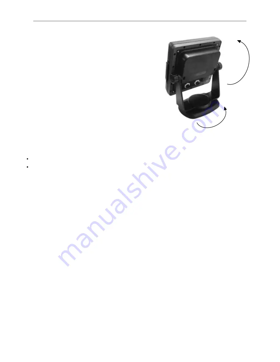
1-3 Removing and replacing the display unit

If the display unit is bracket mounted then the 
display unit can easily be removed and replaced 
for security or protection.

Removing the display unit:

Turn the Explorer 660 off (see section 2-1)

Push the dust cover over the display unit.

Hold the display unit and remove the knobs 
from the mounting bracket. 

Unplug each plug from the back of the 
display unit by turning the locking collar 
anticlockwise and pulling the plug out.

Push the attached dust covers over the 
exposed ends of the plugs to protect them.

Store the display unit in a dry clean place, 
such as the optional Northstar carry bag.

Replacing the display unit

Remove the dust covers from the plugs. Plug the 
plugs into the back of the display unit:


Match the plug color to the socket color.


Insert each plug and turn the locking collar 
clockwise.


Nothing will be damaged if a cable is 
plugged into the wrong socket by mistake.

Hold the display unit in place in the mounting 
bracket. Fit the mounting bracket knobs into 
the display unit and do up the knobs loosely. 

Adjust the tilt and rotation of the display for 
best viewing, then hand tighten the knobs 
on the mounting bracket. Remove the dust 
cover.

Mounting
 bracket

Knob

Adjust
tilt, then 
tighten 
knobs

Adjust
rotation

Summary of Contents for Explorer 660

Page 1: ...www northstarnav com Explorer 660 Chartplotter and Fishfinder Installation and Operation Manual ...

Page 2: ...void possible injury or death WARNING WARNING indicates a potentially hazardous situation which if not avoided could result in death or serious injury CAUTION CAUTION indicates a potentially hazardous situation which if not avoided could result in minor or moderate injury CAUTION CAUTION used without the safety alert symbol indicates a potentially hazardous situation which if not avoided may resul...

Page 3: ...13 3Navigation Chart 17 3 1 Introduction to navigating 17 3 2 Chart display 18 3 3 Distance and bearing calculator 20 3 4 GOTO Navigating to a point or along a route 20 3 5 Projected course 21 3 6 Tracks and tracking 21 4Navigation Highwaydisplay 22 5Navigation Waypoints 23 5 1 Waypoints display 23 5 2 Managing waypoints 24 5 3 Navigating to a waypoint 25 6Navigation Routes 26 6 1 Routes display 2...

Page 4: ...40 9 3 Sonar Bottom display 40 9 4 Sonar 50 200 display 41 9 5 Sonar A Scope display 41 10Datadisplay 42 11Fueldisplay 43 12Tidesdisplay 44 13Usercarddisplay 45 14Aboutdisplay 46 15SettinguptheExplorer660 47 15 1 Setup System 47 15 2 Setup Chart 49 15 3 Setup Sonar 51 15 4 Setup GPS 53 15 5 Setup Fuel 54 15 6 Setup Track 55 15 7 Setup Logs 55 15 8 Setup Alarms 56 15 9 Setup Units 57 15 10 Setup Co...

Page 5: ...ting the GPS antenna and transducers 64 16 5 Wiring the power data cable 66 16 6 Systems of several instruments 67 AppendixA Specifications 68 AppendixB Troubleshooting 70 B 1 General problems 70 B 2 GPS navigation problems 71 B 3 Sonar fishfinding problems 71 B 4 Fuel consumption problems 73 AppendixC Glossaryandnavigationdata 74 ...

Page 6: ...bearings Should the information not agree then the discrepancy must be resolved before proceeding any further Sonar fishfinder The accuracy of the sonar depth display can be limited by many factors including the type of the transducers the location of the transducers and water conditions It is the user s responsibility to ensure the Explorer 660 transducers are installed and used correctly Fuel Co...

Page 7: ...The Explorer 660 receives GPS position information from an external GPS antenna and displays the boat s position and speed The Explorer 660 can navigate to a point or can navigate along a route When the boat is navigating to one of these points the Explorer 660 displays course information for the helmsman to follow The Explorer 660 can control an autopilot Sonarfishfinding The Explorer 660 has a 5...

Page 8: ... 660 has two card slots and can use two plug in cards at the same time It does not matter which slot a card is inserted in Turn Explorer 660 off see section 2 1 Remove cover from right side of case 1 2 3a 3b Pull old card out of its slot Put the old card in its case 4 Hold cover correct way round push back in place Turn Explorer 660 on see section 2 1 To insert card into front slot Hold card with ...

Page 9: ...vers over the exposed ends of the plugs to protect them 6 Store the display unit in a dry clean place such as the optional Northstar carry bag Replacing the display unit 1 Removethedustcoversfromtheplugs Plugthe plugsintothebackofthedisplayunit Matchtheplugcolortothesocketcolor Insert each plug and turn the locking collar clockwise Nothing will be damaged if a cable is plugged into the wrong socke...

Page 10: ...navigating to a point waypoint or along a route see section 3 4 For sonar display Select a sonar operating mode see section 8 1 Create an instant waypoint at the boat position see section 5 2 1 Man overboard MOB see section 2 3 Turn Explorer 660 on and off see section 2 1 adjust the backlighting see section 2 2 In this manual Press means to push the key for less than a second Hold means to hold the...

Page 11: ...NTER to confirm Press twice to return to the maximum backlight setting MOB will not work if the Explorer 660 does not have a GPS fix 1 Press The Explorer 660 stores the boat s position as a waypoint called MOB 2 The Explorer 660 changes to the chart display with the MOB waypoint at the centre of the chart The chart zooms in for accurate navigation If the chart can not show the required small scale...

Page 12: ...at the bottom of the display Otherwise the Explorer 660 functions normally If both GPS and sonar simulation are selected Simulate flashes at the bottom of the display To start and stop Simulate mode see section 15 14 2 4Alarms When the Explorer 660 detects an alarm condition it displays a warning message on the display the internal beeper sounds and any external beepers or lights operate Press ESC...

Page 13: ...Operation Manual 13 To show a display press DISPLAY press or to select the type of display to show Chart Sonar or Other press or to select the display from the list then press ENTER To return to the chart display press ESC 2 6Themaindisplays ...

Page 14: ...Northstar Explorer 660 Installation and Operation Manual 14 Highway Fuel Data Waypoints Routes Satellite Tides User card About ...

Page 15: ...If Chart is the active window then press DISPLAY twice to make Sonar the active display If Sonar is the active window then press DISPLAY twice to make Chart the active display Chart display is active Yellow border Yellow border 2 6 2Favoritedisplays The Explorer 660 has a list of commonly used displays called favorite displays There can be up to six favorite displays and three can be selected by t...

Page 16: ...Press ENTER to display a menu of the data that can be shown in the field c Select the data to show in the field select None to leave the field empty iii Repeat the above step to set the other data fields Press ESC Tip If less than the maximum number of lines of data are used the data will take up less of the display area 5 Press ESC to return to the chart display Thecompass When the boat is navigating...

Page 17: ...he Goto see section 3 4 Followingaroute A route is a list of waypoints that the boat can follow see section 6 1 To create waypoints before creating the route see section 5 2 1 2 To create a route see section 6 2 1 3 To start the route see sections 3 4 or 6 3 1 When the Explorer 660 is navigating the chart data and highway displays show navigation data The chart shows The boat position The waypoint...

Page 18: ...the centre of the chart As the boat moves through the water the chart automatically scrolls to keep the boat in the centre of the chart The cursor see below is turned off Cursor mode The keys and are called cursor keys To switch to cursor mode in the chart display hold down a cursor key The cursor appears and moves away from the boat Press the key which points in the direction that the cursor will...

Page 19: ... stored information about the selected place press MENU and select Chart info see section 3 2 5 To display a tide chart for a selected tide station select Tide height from the chart info Minutes to 3 decimal places about 2 m 6 ft resolution Degrees 36 29 637 S 175 09 165 E Latitude Longitude 36 29 684 S 175 09 201 E When reading the boat position make sure the position is not the cursor position 3...

Page 20: ...ng a route Startingtonavigate Navigating to a point on the chart 1 Press ESC until the chart display is displayed 2 Move the cursor to the destination point 3 Press GOTO AUTO and select Goto cursor Navigating to a waypoint See section 5 3 1 Navigating along a route See section 6 3 1 4 To remove the last leg from the course press MENU and select Remove 5 Repeat the above two steps to enter the whol...

Page 21: ...ld up to 2000 points and is intended to record the normal progress of the boat Tracks 2 3 4 and 5 can hold up to 500 points each and are intended to record sections to be retraced accurately for example entering a river mouth Tip Record the tracks in good conditions When recording is on and the track becomes full then recording continues and the oldest points in the track are deleted 3 6Tracksandt...

Page 22: ...y CDI lines parallel to the boat s plotted course see Appendix C CDI The CDI lines are like a highway over the water where the boat will move Optional data header see section 2 6 3 Boat position is at the bottom centre of the display Boat s plotted course to destination The highway display shows Destination waypoint Optional compass see section 2 6 3 CDI scale WARNING The highway display does not ...

Page 23: ... 15 8 A display option Controls how the waypoint is displayed when the Waypoints setup option is set to Selected see section 15 2 Off The waypoint is not displayed Icon The waypoint icon is displayed I N Icon and Name The waypoint icon and name are displayed If there are many waypoints use this feature to select which waypoints are displayed on the chart Note The other choices for the Waypoints se...

Page 24: ...display edit the waypoint see section 5 2 3 and change the latitude and longitude 5 2 3Editingawaypoint Editing a waypoint from the chart display 1 In the chart display move the cursor to the waypoint to edit 2 Press MENU and select Edit 3 Change the waypoint data see section 5 2 7 Select Save Editing a waypoint from the waypoints display 1 In the waypoints display press or to highlight the waypoi...

Page 25: ...t 5 2 8SortWaypoints To change how the waypoints list is displayed 1 Press MENU and select Sort by 2 Select how to display the list Name In alphabetical order by name Icon Grouped by icon type Distance In order of distance from the boat An arrow at at the top of a column indicates how the waypoints are sorted 5 3 1Startingtonavigatetoawaypoint From the chart or highway display 1 Press GOTO AUTO an...

Page 26: ...i Move the cursor to where the new route waypoint will be iii Press ENTER 6 Navigation Routes 6 2Managingroutes A route is a list of waypoints that the boat can navigate along Routes can be created changed and deleted The Explorer 660 can have up to 25 routes Each route can have up to 50 waypoints A route can Start and stop at the same waypoint Include waypoints more than once The Explorer 660 can...

Page 27: ...s ENTER ii Change the name if necessary iii Press ENTER 4 To insert a waypoint in the route i Select where the waypoint will be To insert the first waypoint in a new route select Leg 1 To insert a waypoint at the end of the route select the unused leg at the end of the list of waypoints Otherwise select the waypoint to insert the new waypoint in front of ii Press ENTER A list of waypoints is displ...

Page 28: ...lect Skip The Explorer 660 starts navigating straight towards the next waypoint on the route 6 2 3Displayingarouteonthechart To view the selected route at the centre of the display 1 In the routes display press or to highlight the route to display Press MENU and select Display Or in the Chart display press MENU select Find then select Route Select a route from the list 2 The Explorer 660 displays ...

Page 29: ...ational Differential beacon DGPS Differential beacons are land based radio transmitters that broadcast correction signals that can be received by a special receiver on the boat Differential beacons are usually only installed near ports and important waterways and each beacon has a limited range The accuracy of the corrected GPS position is typically better than 2 to 5 m 6 to 16 ft 7 Satellites GPS...

Page 30: ...he GPS position caused by satellite geometry A low value indicates a more precise fix a high value a less precise fix Status of GPS antenna for example Acquiring GPS fix No GPS If the unit is in GPS Simulate mode it displays GPS Simulation see section 2 5 Positions of visible GPS satellites Outer circle is horizon Inner circle is 45 elevation Centre is directly above North is at top of display If ...

Page 31: ... 8 5 echoes different fish types different bottom types wrecks and seaweed see section 8 2 noise water clarity and bubbles see section 8 2 Cruise FishingandManualModes The Explorer 660 has three sonar operating modes Cruise mode Use this when on the move The Explorer 660 automatically adjusts its settings to compensate for water clarity and to display the bottom Fishing mode Use this when fishing ...

Page 32: ...m the same area of bottom This produces a flat bottom trace on the display The screen shot shows a typical sonar display with the Fish symbols turned Off Bottom Large school of fish Strengthofechoes The colors indicate differences in the strength of the echo The strength varies with several factors such as the Size of the fish school of fish or other object Depth of the fish or object Location of ...

Page 33: ...ks and ledges because this frequency reduces the shadow effect considerably Frequencyandconewidth Sonar display of same area fish is visible on the display fish is hidden by the strong echoes off the bottom and is not shown on the display Example of shadows fish is visible on the display Water Cone width Cone width Depth at 50 kHz at 200 kHz 25 20 5 50 40 10 100 80 20 150 130 30 200 170 40 300 250...

Page 34: ...h minimal loss of the return signal However it produces a lower definition display with more shadow compared to the 200 kHz frequency This means that a group of small fish for example could be displayed as a single item while any fish very close to the bottom may not be found at all This frequency is useful for getting a deep wide overview of the area so that any areas of interest can be identifie...

Page 35: ...inute ago 30 seconds ago Now Comparison of the same fish scenario displayed at different frequencies 50 kHz display Dual sceen 200 kHz display 50 200 kHz display 50 200 display Note the wider bottom trace Note the smaller defined fish arches and more bottom detail ...

Page 36: ...ng through the cone shaped ultrasonic pulse is displayed as a fish arch The 50 kHz frequency uses a wider cone than the 200 kHz frequency This makes the fish arches easier to see A fish arch starts when a fish enters the weak edge of the sonar cone generating a weak echo that is displayed as the start of the fish arch As the fish moves closer to the middle of the cone the distance between the tran...

Page 37: ...anually 1 Press ENTER to display the gain window 2 Press or to select the setting to adjust 3 Press or adjust the setting If the Explorer 660 is in Cruise or Fishing modes it will stop adjusting gain and threshold automatically but will continue to adjust range automatically Tip Use the A scope display to help set gain or threshold manually see section 8 5 2 To revert to automatic Either press GOT...

Page 38: ... to adjust the settings for see section 15 3 2 Select the sonar display see section 2 6 If necessary press or to adjust range so that the bottom is displayed 3 Press MENU select Sonar splits then select Split A scope 4 Press ENTER to display the Gain window To adjust gain or threshold for a frequency press or to select the setting to adjust then press or to change the setting Threshold line Gain l...

Page 39: ...io c Press ENTER Sonar history display at a single or mixed frequency not split see section 9 1 Sonar split display history plus a zoomed section see section 9 2 Sonar split display history plus a flat bottom trace in a zoomed section section 9 3 Sonar split display histories at 50 and 200 kHz frequencies section 9 4 Sonar split display history plus echo strength section 9 5 9 1Sonarhistorydisplay...

Page 40: ...m lock on or off 1 Press MENU and select Bottom lock 2 Select On or Off or If Bottom lock is on pressing or will turn it off 9 3SonarBottomdisplay The display shows the sonar history on the right and the bottom signal as a flat trace in the centre of the zoom section on the left The flat trace make it easy to compare the echo strengths shown in the bottom signals This can help to identify the type...

Page 41: ...echoes above this strength will display as the maximum signal strength Use the A Scope while adjusting the gain and threshold settings manually see section 8 5 Fishrecognition The echo strengths shown on the A scope can be useful in recognising the type of fish Different species of fish have different sizes and shapes of swim bladders The air in the swim bladder reflects the ultrasonic pulse so th...

Page 42: ...minutes To show the data display press DISPLAY select Other then select Data To select what data is displayed 1 Press MENU and select Data setup 2 Change a data field i Press the cursor keys to highlight the field ii Press ENTER to display a menu of the data that can be shown in the field iii Select the data to show in the field select None to leave the field empty 3 Repeat the above step to set t...

Page 43: ...ning in the tank s Flow shows the fuel consumption per hour For twin engine installations the fuel flow for each engine is shown separately This is useful for checking that both engines are under the same load Economy is the distance travelled per unit of fuel used The Explorer 660 calculates this from the boat speed and fuel used The bigger this number the better the fuel economy Adjust the throt...

Page 44: ... MENU and select Chart info 5 Select Tide height The tides display shows data for the chosen date Choosing the date of the tide chart 1 Press MENU 2 Select Today Next day or Prev day To choose a different date from these select Set date edit the date press ENTER Moon phase for moon at the current time on the chosen date Height and time of highest high water and lowest low water on tide chart Tide ...

Page 45: ... the Explorer 660 until loaded into the Explorer 660 with the LOAD command see below Savingdatatotheusercard This saves all the Explorer 660 s waypoints all the Explorer 660 s routes or one of the Explorer 660 s tracks to one file on the user card 1 Press MENU and select Save 2 Select Waypts Routes or Tracks 3 For Tracks select the track number to save 4 The new file is created Change the name if ...

Page 46: ...ich route to keep A track file The new track will replace the existing track in the Explorer 660 To load a file to the Explorer 660 1 Select the file to load 2 Press MENU and select Load Deletingafilefromtheusercard 1 Select the file to delete 2 Press MENU and select Delete 3 Select Yes to confirm Readingthefileinformation This reads the file names from the user card and displays them Reading does...

Page 47: ...play changes when you press the DISPLAY key and use the display menu to choose a new display see section 2 6 The options are Off The display only changes when you press finally ENTER to choose a display On The display changes each time you highlight another display in the display menu Sonar Disable any sonar transducer and disable sonar functions A sonar transducer is fitted Enable sonar operation...

Page 48: ...options Factory default settings are shown where applicable Simulate see 15 14 Favorites see 15 13 GPS see 15 4 Logs see 15 7 Units see 15 9 Time see 15 12 Comms see 15 10 Track see 15 6 Smartcraft Fuel see 15 5 Sonar see 15 3 System see 15 1 Alarms see 15 8 Chart see 15 2 Water depth see 15 2 ...

Page 49: ...Scale The CDI Scale is described in Appendix C CDI The options are 0 05 0 1 0 2 0 5 1 0 2 0 4 0 and 10 0 distance units Plottermode Occasionally it is desirable to use a chart scale which is not available on a chart card Examples are To zoom in to a small scale to track very small boat movements If there is no detailed chart for an area for example when crossing an ocean If Plotter mode is On then...

Page 50: ...cast on any NMEA VHF transmitter will be the same as the coordinates on a WGS 84 chart WARNING When you change to a chart with a different datum change the Explorer map datum again Mapshift Some charts have consistent position errors To correct this apply a map shift After a map shift The positions of cartographic features such as land rocks buoys and depth contours move on the Explorer 660 chart ...

Page 51: ...um and Large Digit size Use this to remove or change the size of the depth display on the sonar displays There is a choice of Small Medium and Large Depth line This is a horizontal line that can be moved up or down using the or cursor keys The depth line can be used to find the depth of a fish or other object shown When in the Sonar Zoom display the depth line marks the centre of the zoomed area I...

Page 52: ... first four pallettes display more detail and each color covers a 1 5 dB signal range The 8 color palette displays less detail and each color covers a 3 dB signal range Interference filter This filters the echo signal to reduce high level spiky interference such as engine noise It can be switched On or Off Pulse length This can be used to specify the length of the transmitted ultrasonic pulse A sh...

Page 53: ... Western Europe StaticNavigation When the boat stops or moves very slowly the calculated GPS speed and course become erratic Static navigation is a number and the options are 0 01 to 99 9 If the boat speed is slower than this the speed is displayed as zero and the course stays unchanged 0 Off The calculated speed and course are always used SpeedandCourseFilter Waves and wind cause the boat speed a...

Page 54: ...el is now in the tank 4 Select Set remaining and update the reading It is essential to do this whenever some fuel is added or removed Otherwise the Fuel display and the Low Fuel Alarm are meaningless 15 5Setup Fuel Clear Used Select Clear used to set Used the amount of fuel used to zero Do this to start measuring the amount of fuel used over a certain time or distance When asked Are you sure selec...

Page 55: ...rded track 1 has up to 2000 points and tracks 2 3 4 and 5 have up to 500 points each Record Off The Explorer 660 stops recording a track 1 to 5 select a track number The Explorer 660 starts recording the boat s course into the selected track Display Off No track is shown on the chart 1 to 5 select a track number The selected track is shown on the chart Plotting Interval The options are Distance or...

Page 56: ...re equals the alarm trigger value Temperature rate rate of change of temperature equals the alarm trigger value Low battery battery voltage is less than the alarm trigger value Low fuel fuel remaining equals the alarm trigger value Loss of DGPS fix Explorer 660 can not receive the DGPS signal beacon WAAS or EGNOS Loss of GPS fix Explorer 660 can not receive the GPS signal this alarm is always on The...

Page 57: ...orer 660 is connected to other Northstar instruments through NavBus or any compatible NMEA instrument Press MENU once or more until the Setup menu is displayed then select Comms NMEA NMEA is generally used with third party instruments see section 16 6 Select On to transmit NMEA sentences for example to an autopilot Otherwise select Off NMEA data Use this to specify which NMEA sentences will be tra...

Page 58: ...easure the water temperature with a thermometer known to be accurate Use the cursor keys to display the temperature readout box then increase or decrease the value to match the measured temperature The temperature can be set from 32 to 99 9 F 0 to 37 7 C with a resolution of 0 1 unit To change the units between F Fahrenheit or C Celsius see section 15 9 Temperaturefilter Water turbulence and curre...

Page 59: ...offset is a depth correction representing the vertical distance between the depth transducer and the location from which the depth is to be measured Enter a positive keel offset value when the transducer is located below the water surface but the total depth is required Enter a negative keel offset value when the depth below the deepest part of the boat is required such as the keel the rudder or t...

Page 60: ...hart display before starting the simulation Then To start the simulation from the boat position press ESC to switch to centre on boat mode To start the simulation from a different point move the cursor to that point on the chart Tip To calculate a heading use the cursor see section 3 3 Tip As the boat moves vary Heading to simulate the boat moving off course Demo Simulates the boat moving along a ...

Page 61: ...ansducer and the GPS antenna In addition install the optional fuel kit to use the Explorer 660 as a fuel computer The Explorer 660 can Drive external beepers or lights for the alarm Send and receive data from other Northstar instruments connected via NavBus The backlight setting is shared see section 16 6 Send NMEA data to an autopilot or other instrument Accept and display NMEA wind data from an ...

Page 62: ...equired see section 16 6 Replacement paddle wheel Northstar s Explorer R310 see section 16 6 C MAP chart cards C MAP user cards 3 V for storing data The older 5 volt cards are not supported Beepers with built in drivers or lights The Explorer 660 outputisswitchedtoground 30V DC and 200 mA maximum If the beepers and lights require more than 200 mA fit a relay 5 m 16 ft extension cable for Northstar...

Page 63: ... in front of the navigator or to the right of the navigator because the LCD display is more readable from these positions Not exposed to the direct sun or water Protected from physical damage during rough sea passages Easy to access the 12 24 V DC power source Convenient to route the transducer cables Flush Mounting 1 Cut a hole in the bulkhead for the display unit using the flush mount template 2...

Page 64: ... Explorer 660 For enhanced performance fit an optional through hull dual frequency sonar transducer and through hull speed temperature transducer Contact the nearest Northstar dealer for more information The sonar transducer cable has a plug with a blue collar Plug this into the connector with a blue nut on the back of the Explorer 660 Turn the collar to lock the connector 16 4MountingtheGPSantenn...

Page 65: ...e cable has two wires with black coverings the black wire pin 1 and the shield covered with heatshrink These wires are con nected within the cable and therefore it does not matter which black wire you use 2 Brown Power out 9 V DC NOT USED 3 White NMEA out 4 Blue NavBus 5 Red Positive power in 10 to 35 V DC 6 Orange NavBus 7 Yellow Auto power in connect to red wire positive power in to enable Auto ...

Page 66: ...he optional fuel kit is fitted Note With auto power the Explorer 660 can not be turned off using the key 2 Wire any external beepers or lights If the current is more than 200 mA fit a relay 3 The power data cable has a plug with a black collar Plug this plug into into the connector with a black nut on the back of the Explorer 660 Turn the collar to lock the connector Main switch Fuse 2 A Red Yello...

Page 67: ...it by clearing the alarm on any instrument which can display that alarm NavBus and the Explorer 660 The Explorer 660 can Display wind speed and direction from an optional Wind instrument such as a Northstar W310 or W315 Receive data from an optional GPS or GPS DGPS source Send data to optional Northstar instruments for example to a repeater NMEA NMEA is an industry standard but is not as flexible ...

Page 68: ...4096 nm for chart chart dependent down to 0 01 nm in plotter mode SONAR FISHFINDING Depth range 0 6 m 2 ft to 1000 m 3300 ft Sonar output Power Variable up to 600 W RMS Dual frequency 50 kHz and 200 kHz Transom transducer cable length 10 m 33 ft Depth acquisition time from startup Typically 2 seconds at 30 m 100 ft Temperature Range 0 to 37 7 C 32 to 99 9 F Resolution of 0 1 unit Speed from paddle...

Page 69: ...74 Ireland 1965 ISTS 061 Astro 1968 ISTS 073 Astro 1969 Johnston Island 1961 Kandawala Kerguelen Island 1949 Kertau 1948 Kusaie Astro 1951 L C 5 Astro 1961 Leigon Liberia 1964 Luzon M Poraloko Mahe 1971 Massawa Merchich Midway Astro 1961 Minna Montserrat Island Astro 1958 Nahrwan Masirah Is Oman Nahrwan United Arab Emirates Nahrwan Saudi Arabia Naparima BWI North American 1927 North American 1983 ...

Page 70: ...ng This troubleshooting guide is written with the assumption that the user has read and understood the relevant sections in this manual It is possible in many cases to solve difficulties without having to send the display unit back to the manufacturer for repair Please follow this troubleshooting section before contacting the nearest Northstar dealer There are no user serviceable parts Specialized...

Page 71: ...d or the required NMEA sentences are not turned on Check NMEA settings see section 15 9 b Check that the instrument is connected correctly 2 7 No DGPS fix or loss of DGPS fix a To receive a DGPS fix WAAS EGNOS must be enabled or an optional DGPS antenna fitted see section 7 b With WAAS EGNOS Boat out of coverage area see section 7 c With WAAS GPS antenna does not have a clear view of the horizon t...

Page 72: ...he display unit will display to indicate that there is no bottom detected A display of the bottom should reappear when in shallower water 3 3 The bottom is displayed too far up the screen The Explorer 660 may have Manual Range selected and the selected Range value is too high for the depth Either change the Explorer 660 to Auto Range or select another depth range see section 8 5 3 4 Bottom echo di...

Page 73: ...ble connectors are securely plugged in and the collar is locked in place The collar must be locked in place to give a watertight connection c A fuel transducer may be clogged If so remove the transducer from the fuel line and gently blow through it in the opposite direction to the fuel flow A fuel filter between the fuel transducer and the fuel tank must be installed as per the fuel installation g...

Page 74: ... Global Positioning System A satellite based navigation tool see section 7 Leg The straight segments of a route between waypoints A route with four waypoints has three legs MOB Man overboard MOB function Starts navigating back to the place where someone fell overboard see section 2 4 NavBus A way of connecting Northstar instruments together to share data see section 16 6 NMEA National Marine Elect...

Page 75: ... 15 8 an alarm will sound if the boat reaches a CDI line COG Course Over Ground Direction in which the boat is moving over the ground CTS Course To Steer Optimum course to steer to return to the plotted course DTG Distance To Go Distance from the boat to the destination ETA Expected Time of Arrival At the destination assuming that SOG and COG remain constant RNG Range to cursor Distance from boat ...

Page 76: ...y Belvidere Rd Southampton SO14 5QY ENGLAND Ph 44 2380 339922 Fax 44 2380 330345 northstaruk northstarnav com AUSTRALIA PO Box 479 Gladesville NSW 2111 AUSTRALIA Ph 61 2 9879 9060 Fax 61 2 9879 9009 northstaraus northstarnav com NEW ZEALAND PO Box 68 155 Newton Auckland Auckland NEW ZEALAND Ph 64 9 481 0500 Fax 64 9 481 0590 northstarnz northstarnav com www northstarnav com ...

Reviews:

Related manuals for Explorer 660