15
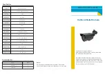
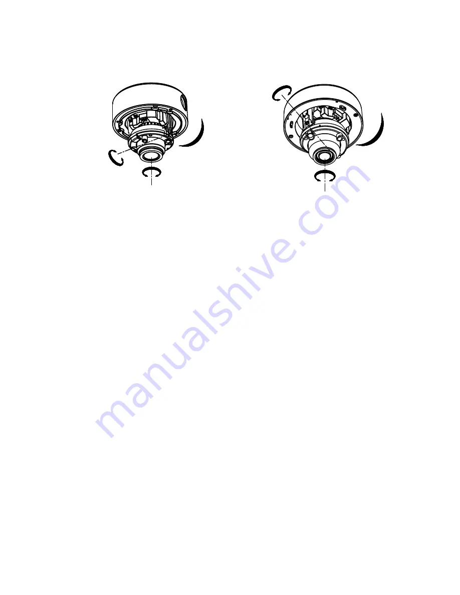
TVIVFDIR120 TVID212IR2
Type I Camera
:
0° to 355°
0° to 355°
0° to 75°
0° to 355°
0° to 340°
0° to 75°
Type II Camera:
Figure 2. 4
3-Axis Adjustment
9.
Fit the black liner on the camera and tighten the screws on
the bubble of the dome camera to finish the installation.
2.1.2
In-Ceiling Mounting
Note:
You need to purchase an in-ceiling mounting bracket separately if
you adopt the in-ceiling mounting.
Steps:
1.
Attach the drill template on the ceiling.
2.
Drill the screw holes and cable holes (optional) in the ceiling
according to the supplied drill template.
Note:
Cable hole is required when adopting ceiling outlet to route the
cable.
3.
Screw the bolts through the mounting bracket by aligning
with the 2 bolt holes. Fit the toggles onto the bolts.
Summary of Contents for TVID212IR2
Page 8: ...7 3 3 9 ADJUST 40 3 3 10 RESET 41 3 3 11 EXIT 41...
Page 43: ...42...