


3
LOCATION:
It is important to consider the prevailing wind directions in the heating season. The Northern Stoker should be placed so that the smoke
exiting the unit will not create problems for you or your neighbours. Consult your Northern Stoker Dealer for suggestions where to
locate the unit.
PAD TO SUPPORT YOUR NORTHERN STOKER:
First, remove the top soil, build a form, and fill it with concrete. The pad should be 5” – 6” (127 – 152 mm) thick and have some wire
mesh or rebar in it. It should be a least 16” (400 mm) in front and 8” (200 mm) on either side of the fuel loading and ash removal doors.
Consult your Northern Stoker Dealer for the local code requirements in your area.
CAUTION! Check before you dig!
Telephone Lines – Hydro Lines – Gas Lines – Water Lines – Sewer Lines – Drainage Tiles
LIFTING TECHNIQUES
TRENCH FOR INSULATED WATER LINES AND ELECTRICAL WIRE:
The trench should be approximately 3’ (914 mm) deep and 18” (457 mm) wide. It can be dug with a shovel or a backhoe. Place all the
dirt to one side of the trench to allow room for working on the other side. Rake the bottom of the trench so it is smooth, no large bumps
or sharp stones.
WATER LINES:
Water line to use
: 1” (25 mm) water line with a minimum rating of 100 psi (689.5 kPa) at 180ºF / 82ºC rating.
Water line insulation
: Must be rated for at least R-8. Cover the insulated pipes with 3” (76 mm) of clean sand to avoid stone punctures.
Contact you Northern Stoker dealer for approved water line insulation.
Burying tip
: When burying your water lines in a low lying and wet area, be sure to insulate and install inside PVC piping.
Burying tip
: When burying your water lines, be sure to sure to label the water lines at each end for ease of installation.
Burying tip:
If installing the water lines underneath a driveway, they should be buried approximately 4’-5’ (1219 – 1524 mm) below
grade. If lines travel through a low or wet area, they should be insulated and installed in a water tight piping.
Burying Tip:
It is easiest to hook up your Northern Stoker when it is mounted on a concrete pad before the trench is dug. If this is not
possible, be sure to leave adequate pipe above the pad to complete the hook-up.
Installation Tip: Be sure to install a furnace fill valve inside your home in the cold water return line preferably close to domestic water
supply. This will aid when filling water into your system (see page 4).
WIRING:
The electrical wire used must be rated for underground and at least12 AWG copper, two wire plus a ground (12/2). Place the electrical
wire in the bottom of the trench and cover with 3” (76 mm) of sand along with the water lines from the Northern Stoker. The electrical
wire must maintain a minimum 24” (610 mm) depth. As with any buried electrical wires you must install a “Caution Buried Electrical
Cable Below” tape over top of the wire.
Always follow the applicable local Provincial and Municipal laws, regulations and codes.
CHIMNEY SPECIFICATIONS:
MODEL 30-30
MODELS 36-42, 48-54
Oliver Macleod – H.T. 6103
Oliver Macleod – H.T. 6103
6” (152 mm) I.D.
8” (203 mm) I.D.
8” (203 mm) O.D.
10” (254 mm) O.D.
24” (610 mm) Long
24” (610 mm) Long
Tested to ULC – S610
Tested to ULC – S610
Use only a chimney suitable for solid fuel. Do not connect to a chimney flue serving another appliance. Place only on non
combustible flooring with adequate support.
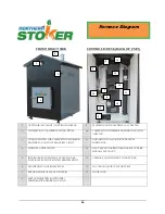
Furnace Installation
CAUTION! Lift between the legs from the side or from the lift hook on the top only! Do NOT lift
from under the “control house” at the rear of the furnace. Ensure that the lifting device is rated
for weight of the furnace and can safely lift and maneuver the Northern Stoker into position.
Maintain the following clearances to combustibles:
Sides – 8’ (2438 mm) Front – 8’ (2438 mm) Back - 8’ (2438 mm)
Summary of Contents for 30-30
Page 23: ...21 Notes...