


OLP 05/00
LUBRICATION
Break-in oil
1. Use one of the following during the first 100 hours
of operation:
a. John Deere Engine Break-In Oil
b. API Service CE oil
c. ACEA Specification E1
2.
Do not use
John Deere PLUS-50 oil or engine oils
meeting API CG4, API CF4, ACEA E3, or ACEA
E2 performance levels during the first 100 hours of
operation of a new or rebuilt engine. These oils will
not allow the engine to break-in properly.
Lubrication - General
1. Use only clean, high quality lubricants stored in
clean containers in a protected area.
2. These oils are acceptable after the first 100 hours:
a. API Service CC/CD single viscosity oils.
b. API Service CD/CG-4/CF-4 multi-viscosity oils.
c. ACEA Specification E3/E2 multi-viscosity oils.
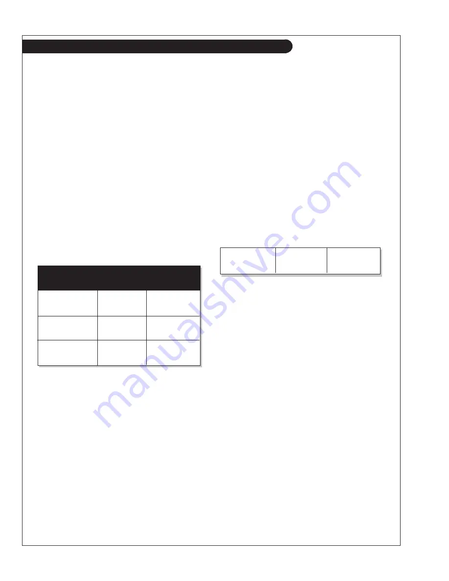
3. Use the proper weight oil for your average operation
temperature.
4. Some increase in oil consumption may be expected
when SAE 5W and SAE 5-20W oils are used. Check
oil level frequently.
5. Never put additives or flushing oil in crankcase.
SP1. CHECK ENGINE OIL LEVEL
1. Check the oil level in the crankcase, with the oil
dipstick, daily.
2. The oil level must be between the “Waffled area” and
the “oo”. Never allow the level to go below the “oo”.
3. Always add the same viscosity of oil as is already in
the crankcase.
SP2. OIL CHANGES
1. Using the oil recommended above, change the
engine oil and filter after the first 50 hours of
operation, the first 100 hours and every 200 hours
thereafter.
Marine Generator Sets:
a. Remove plug from outlet in base frame. Screw in
owner-supplied drain hose.
b. Open valve at oil pan outlet. After oil has been
drained into suitable container, close valve, remove
drain hose and replace plug in base frame outlet.
c. Refill engine with recommended oil.
4. Engine Lube Oil Capacity:
SP3. CHANGING OIL FILTER
1. Change the lube oil filter every 200 hours.
2. Use a filter wrench to remove old filter. Dispose of
filter in approved manner.
3. Make sure the gasket from the old filter is removed
and discarded.
4. Lubricate the rubber gasket on the new filter and screw
it on nipple until gasket meet the sealing surface.
5.
Using hands only, no wrench, tighten filter one-half turn
farther. Overtightening can do damage to filter housing.
6. Fill engine with recommended oil. Start engine and
check for leakage. Stop engine and check oil level.
Add additional oil if necessary.
SP4. AIR Cleaner
1. Inspect air cleaner every 100 hours. Replace filter
every 600 hours, or yearly, whichever comes first.
2. Clean the rubber tube at the cleaner. Loosen the hose
clamp and the attaching strip for the cleaner.
3. Make sure the rubber tube is in good condition and
that new filter is absolutely clean and installed prop
-
erly.
4. Start the engine and check for leaks.
NOTE:
Make absolutely sure no impurities enter
the engine while changing the element. Do not
run the engine with the air cleaner removed.
Air
Single Multi
Temperature Viscosity
Viscosity
Above 32°F
(0°C)
SAE-30W SAE15-40W
-10°F to 32°F
(-23°C to 0°C)
SAE-10W SAE10-30W
Below -10°F
(-23°C)
SAE-5W SAE5-20W
445 Series
14 qts.
13.2 liters
668 Series
18 qts.
17.0 liters
10
Servicing
2. During intermittent cold weather operation, change oil
every 100 hours or six weeks, whichever comes first.
3. Change oil at any seasonal change in temperature when
a new viscosity of oil is required.
Propulsion Engines
w/Optional Drain Pump:
a. Remove dipstick.
b. Unscrew dipstick tube and insert the hand pump to
the bottom of the oil pan. Drain by pumping.
c. Replace dipstick tube and dipstick.
d Refill engine with recommended oil.
Summary of Contents for OLP LP445
Page 29: ...OLP 05 00 27 Wiring Diagrams DC Engine Wiring Diagram 12 Volt Lugger LP668 Drawing C 4363B...
Page 30: ...OLP 05 00 28 DC Engine Wiring Diagram 12 Volt Lugger LP445 Drawing C 4364A Wiring Diagrams...
Page 31: ...OLP 05 00 Wiring Diagrams 29 DC Engine Wiring Diagram 24 Volt Lugger LP668 Drawing C 4370A...
Page 32: ...OLP 05 00 Wiring Diagrams 30 DC Engine Wiring Diagram 24 Volt Lugger LP445 Drawing C 4371...
Page 34: ...OLP 05 00 32 Notes...
Page 35: ......


