


Operation: Using the Stop Block
IMPORTANT: R
ea
d
page
5
before
you p
r
oce
ed to
t
h
i
s section.
Purpose of the Stop Block
The stop
block prevents the material from rotating while a forming die in the
ha
n
dl
e
bends
the material around either the center pin or
a
n
oth
er
die
that
has
been installed on the center pin.
When
you are
b
en
d
i
n
g material,
the
stop block will
be
located (using a hitch
pin) at one of the five large holes in
the m
i
dd
l
e of
the
ring
a
s
s
em
b
l
y
'
s loop.
(The large hole at the open end of the loop is
for the center
p
i
n
.
)
You
will
have
to
detemnine by trial which hole you will
use,
d
epe
nd
i
n
g
on the thick·
ness of
the
material being bent. the size
of
the ce
n
ter
-
p
i
n die, and the orien
talion of
the s
t
op
b
l
ock
.
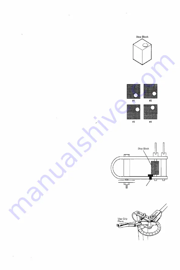
Positioning the Stop Block
The
stop block can be placed in several orientations by rotating
it
on
the
hinge pin or by turning it upside down and rotating it on the pin. However
only four of the possible orientations are
used
when bending. Throughout
this manual, those four o
r
i
e
nta
tion
s
are identdied
by
a
number (
r
efe
r
to the
illustration
at righ
t
)
.
CAUTION: Always
posrtion
the
stop block
of/-center
to the
r
ight
no
m
a
tt
e
r
which face is used against the m
at
e
r
ia
L If
positioned
off·
center to the left, the block
will
tu
r
n and
the material will
slip in
t
h
e
B
e
nd
er
.
To position
t
h
e stop block (that
is,
to select
the proper or
i
en
ta
ti
on
and
t
h
e
proper hole
in
the loop):
1.
Connect
the
handle
to the center
pin of the
loop, with the appropriate
die
i
n
s
t
a
ll
ed
on the center pi
n.
2.
I
ns
ta
ll the
appropriate die at the
a
pprop
r
i
at
e
hole in the handle.
3.
Insert
a
piece
of the material to be formed. With the
handle all
t
h
e way
back (counterclockwise),
i
n
st
a
ll
the stop block - in
t
h
e
orientation that
places it as close to the center pin as possible.
IMPORTANT: Atways
use the loop hole that places the slop block
as
close to the center
pin
or die as possible, while l
eavi
n
g space for the
material to be
inserted.
If there is too much space between
the s
t
op block
and
the center pin
or
d
i
e
,
turn the b
l
oc
k
to a different
orientation or move the block o
n
e
h
o
l
e
c
los
e
r
t
o
t
h
e ce
n
t
e
r
.
Positioning the Block Support
The block
s
u
ppo
rt
must be located
under
the stop block
as
shown,
to keep
the
block
c
en
t
e
r
e
d
vertically in the
l
o
o
p
.
Install the support
in
the app
r
opr
iat
e
l
oop hole where it
will
support the stop
block
but not interfere with inserting the
hitch pin
all the
way t
h
r
o
u
gh
the
block hole and the lower hole
in the loop.
Clamping
If the slop block is positioned correctly, the material wiil normally not have to
be clamped
in
the Bender. However,
when
you are making special bends or
need precise dimensions, it
is
helpful to
clamp
the material against the
s
t
op
block
using a vise-grip pliers
as
shown at rig
h
t
.
6
Stop Block Orientations
Positioning
the Block Support
Block Support
Clamping the Material


