background image

90

  Chapter 4  Operating the Passport 8000 Series switch

316314-E Rev 01

Troubleshooting

The following sections provide troubleshooting information for some of the more 
common problems that you may encounter with the Passport 8000 Series switch.

LED indications of problems

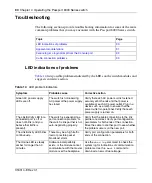
Table 14

 lists possible problems indicated by the LEDs on the switch modules and 

suggests corrective action.

Topic

Page

LED indications of problems

90

Apparent module failure

91

Failure to get a login prompt from the Console port

92

Cable connection problems

93

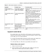
Table 14   

LED problem indicators 

Symptom

Probable cause

Corrective action

Green AC power supply 
LEDs are off.

The switch is not receiving 
AC power or the power supply 
has failed.

Verify that each AC power cord is fastened 
securely at both ends and that power is 
available at each AC power outlet. Plug in a 
device such as a lamp to ensure that the 
power outlet is operational. Verify that each 
power supply is turned on.

The Link/Activity LED for a 
connected port is off or 
does not blink (and you 
believe that traffic is 
present).

The switch is experiencing a 
port connection problem, or 
the switch’s link partner is not 
auto-negotiating properly.

Verify that the cable connections to the link 
partner are correct. Verify port configuration 
parameters for both ends of the connection. 
Move the cable to another port to see whether 
the problem occurs on the new port.

The Link/Activity LED blinks 
continuously.

There may be a high traffic 
load or possible packet 
broadcast storm.

Verify port configuration parameters for both 
ends of the connection.

The Online LED is steady 
amber for longer than 3 
minutes.

Software incompatibility 
exists, or the module cannot 
communicate with the master 
module over the backplane.

Use the 

show log

 command to check the 

system log for indications of communication 
problems. Use the


boot


command to 

download a new software image.

Summary of Contents for Passport 8000 Series

Page 1: ...Part No 316314 E Rev 01 March 2006 4655 Great America Parkway Santa Clara CA 95054 316314 E_Rev_01 Installing and Maintaining the Passport 8000 Series Chassis...

Page 2: ...t s or circuit layout s described herein International regulatory statements of conformity This is to certify that the Nortel Networks 8000 Series chassis and components installed within the chassis w...

Page 3: ...ass A product In a domestic environment this product may cause radio interference in which case the user may be required to take appropriate measures Achtung Dieses ist ein Ger t der Funkst rgrenzwert...

Page 4: ...rds Metrology and Inspection BSMI CNS 13438 Class A MIC notice for 8010 8006 8003 chassis Republic of Korea only This device has been approved for use in Business applications only per the Class A req...

Page 5: ...nt 8010 8006 and 8003 chassis Mexico only The following information is provided on the devices described in this document in compliance with the safety requirements of the Norma Oficial M xicana NOM E...

Page 6: ...2100 Fax 52 5 480 2199 Embarcar a Model 8003AC 100 240 VCA 50 60 Hz 9 A max por fuente de poder Model 8004AC 100 240 VCA 50 60 Hz 12 6 A max por fuente de poder una fuente una fuente configuraciones d...

Page 7: ...reate derivative works or modifications unless expressly authorized or d sublicense rent or lease the Software Licensors of intellectual property to Nortel Networks are beneficiaries of this provision...

Page 8: ...destruction c Customer is responsible for payment of any taxes including personal property taxes resulting from Customer s use of the Software Customer agrees to comply with all applicable laws inclu...

Page 9: ...Revision history March 2006 CR Q01300584 Change in documentation Removed Pressing the Reset button causes a warm restart Added the following Note Pressing the Reset button causes a cold restart...

Page 10: ......

Page 11: ...r supplies 31 Fan trays 33 Chapter 2 Installing the 8010 8006 and 8003 chassis 35 Preparing to install the 8010 8006 and 8003 chassis 35 Shipment contents 36 Supplying equipment 39 Management console...

Page 12: ...uirements 58 Installing the chassis 58 Mounting the 8010co chassis in a two post rack 59 Mounting the 8010co chassis in a 19 inch rack 61 Mounting the 8010co chassis in a Hendry rack 64 Installing the...

Page 13: ...endix A Technical specifications for the Passport 8000 Series Chassis 95 Model 8003AC power supply 96 AC input power specifications 96 DC output power specifications 96 Model 8004AC power supply 97 AC...

Page 14: ...09 Physical specifications 110 Environmental specifications 110 International regulatory requirements 111 Electromagnetic emissions 111 Electromagnetic immunity 111 Safety agency certification 112 800...

Page 15: ...s to the chassis 8003 chassis 46 Figure 14 Aligning the rack mounting brackets with the equipment rack 8010 chassis 47 Figure 15 Aligning the rack mounting brackets with the equipment rack 8006 chassi...

Page 16: ...brackets 68 Figure 36 Location of 8010co chassis ground studs 69 Figure 37 Chassis and 8004DC power supply grounding example 71 Figure 38 Chassis and AC power supply grounding example 73 Figure 39 Rac...

Page 17: ...P 57 Table 10 Environmental requirements 58 Table 11 Item description for chassis and 8004DC power supply grounding 72 Table 12 Item description for chassis and AC power supply grounding 74 Table 13 8...

Page 18: ...18 Tables 316314 E Rev 01...

Page 19: ...ace fan trays power supplies modules gigabit interface converters and media dependent adapters This guide also describes some of the routine tasks of operating the Passport 8000 Series switch and incl...

Page 20: ...ons you need and print them on most standard printers Go to Adobe Systems at the www adobe com URL to download a free copy of the Adobe Acrobat Reader bold Courier text Indicates command names and opt...

Page 21: ...gi URL then click on Technical Support From the Technical Support page you can open a Customer Service Request online or find the telephone number for the nearest Technical Solutions Center If you are...

Page 22: ...22 Preface 316314 E Rev 01...

Page 23: ...kplane and a power backplane The number of bays for power supplies and the number of fan trays depends on the chassis type The Passport 8000 Series chassis comprise the following chassis types 8010co...

Page 24: ...h Modules 312749 J The 8010co chassis has three bays for either AC or DC power supplies The 8010co chassis supports the following AC power supplies 8004AC 8005AC The 8010co chassis supports the follow...

Page 25: ...Passport 8000 Series Chassis 312751 D or Installing a DC Power Supply in a Passport 8000 Series Chassis 313070 D The 8010co chassis has two fan trays for cooling refer to Installing a Fan Tray in an...

Page 26: ...es switch fabric modules For complete information about Passport 8600 modules and instructions for installing them see Installing Passport 8600 Switch Modules 312749 J The 8010 chassis has three bays...

Page 27: ...tch 312752 D Figure 2 on page 28 also shows the location of customer replaceable components in the 8010 chassis Caution The 8004 and 8005 power supplies have different power ratings Therefore Nortel N...

Page 28: ...modules and two slots for installing 8691SF or 8692SF switch fabric modules The top four slots allow you to install 8600 interface modules Slots 5 and 6 are reserved for Passport 8000 Series switch f...

Page 29: ...rt 8600 Release 3 7 Therefore Nortel Networks recommends that you use the 8004 or 8005 power supply with these modules Caution The 8004 and 8005 power supplies have different power ratings Therefore N...

Page 30: ...ssport 8000 Series Switch 312752 D Figure 3 also shows the location of customer replaceable components in the 8006 chassis Figure 3 8006 chassis and components 8003 chassis As shown in Figure 4 on pag...

Page 31: ...Passport 8000 Series Chassis 312751 D and a single 8003 fan tray for cooling refer to Installing a Fan Tray in an 8000 Series Switch 312752 D Figure 4 also shows the location of customer replaceable c...

Page 32: ...s for the Passport 8000 Series Chassis on page 95 Note The 8001AC and 8002DC power supplies have not been tested with Passport 8600 modules released since Passport 8600 Release 3 7 Therefore Nortel Ne...

Page 33: ...ort 8000 Series chassis A control monitor circuit board in the fan tray reports temperature and fan operating status to the network management software A green LED indicates that the fan is operating...

Page 34: ...34 Chapter 1 Passport 8000 Series chassis hardware components 316314 E Rev 01...

Page 35: ...003 chassis Before beginning the installation verify that Your shipment is complete and undamaged You have the cables tools and other equipment that you need Your installation site meets the physical...

Page 36: ...iner Table 2 Chassis shipping accessories 8010 8006 8003 Figure 5 on page 37 Figure 6 on page 38 and Figure 7 on page 39 illustrate the items in the chassis shipping container Check Accessory Use to B...

Page 37: ...Maintaining the Passport 8000 Series Chassis Figure 5 Items in the 8010 chassis shipping container 9073FB 1 2 6 4 1 Cable adapter 2 Rack mounting brackets 3 Console cable 4 Screws x14 for brackets 5...

Page 38: ...316314 E Rev 01 Figure 6 Items in the 8006 chassis shipping container 1 Cable adapter 2 Rack mounting brackets 3 Console cable 4 Screws x10 for brackets 5 Screws x10 for equipment rack 6 Cable guide...

Page 39: ...the cables tools and other equipment that you will need Management console To configure startup options and to monitor the results of startup diagnostics you can attach an optional PC laptop VT 100 co...

Page 40: ...uction Electronic Industries Association EIA standard hole spacing Width of 19 in 48 26 cm and depth of 24 in 60 96 cm Site requirements Ensure that the installation site meets the space electrical an...

Page 41: ...C power Table 3 For additional electrical requirements see Appendix A Technical specifications for the Passport 8000 Series Chassis on page 95 Environmental requirements The installation site must mee...

Page 42: ...chassis can be mounted onto any appropriate flat level surface that can safely support the weight of the chassis its components and its attached cables as long as there is adequate space around the un...

Page 43: ...ipment rack 10 screws and washers extra screws are shipped with the 8010 chassis Phillips screwdriver Table 6 list the maximum number of chassis installed in a 7 foot rack To install the chassis in a...

Page 44: ...in the chassis Figure 8 Figure 9 and Figure 10 on page 45 Figure 8 Positioning the rack mounting brackets 8010 chassis Figure 9 Positioning the rack mounting brackets 8006 chassis Note Each bracket fi...

Page 45: ...rack mounting brackets 8003 chassis 2 Insert and tighten the supplied flat head screws to fasten each bracket to the chassis Figure 11 Figure 12 and Figure 13 on page 46 Figure 11 Attaching the rack m...

Page 46: ...ing the chassis in position align the flanged end of each mounting rail with two holes on each side of the vertical rack support It is easiest to complete this step with two people Make sure that the...

Page 47: ...t 8000 Series Chassis Figure 14 Aligning the rack mounting brackets with the equipment rack 8010 chassis Figure 15 Aligning the rack mounting brackets with the equipment rack 8006 chassis Figure 16 Al...

Page 48: ...E Rev 01 5 Insert and tighten the rack mounting screws with a Phillips screwdriver Figure 17 Figure 18 and Figure 19 on page 49 Figure 17 Installing the 8010 chassis in an equipment rack Figure 18 In...

Page 49: ...Installing the cable guides The cable guides keep cable clusters fastened and out of the way but still accessible for maintenance To install the cable guides 1 Loosen but do not remove the rack mount...

Page 50: ...21 Loosening the rack mounting screws 8006 chassis Figure 22 Loosening the rack mounting screws 8003 chassis 2 Slide the guide onto the loosened screws Figure 23 Figure 24 on page 51 Figure 23 Slidin...

Page 51: ...s Figure 24 Sliding the cable guide onto the screws 8003 chassis 3 Tighten the screws to secure the guide to the chassis Figure 25 Figure 26 and Figure 27 on page 52 Figure 25 Securing the cable guide...

Page 52: ...52 Chapter 2 Installing the 8010 8006 and 8003 chassis 316314 E Rev 01 Figure 27 Securing the cable guide to the chassis 8003 chassis 10247FA...

Page 53: ...al requirements The sections that follow provide information to help you prepare for installation Topic Page Preparing to install the 8010co chassis 53 Installing the chassis 58 Grounding the 8010co c...

Page 54: ...10 foot console serial cable Connect an optional management console Screws and hardware 12 Phillips head screws 12 self tapping hex head screws 12 clipnuts NOTE The hardware required for mounting the...

Page 55: ...ble management bracket and screws x 4 2 Installation shelf 3 Bottom bezel 4 Phillips head screws for mounting chassis and installation shelf in a standard 19 inch rack x 16 5 Hex head screws for mount...

Page 56: ...010co chassis in a standard rail type equipment rack You will need a nutdriver to install the 8010co chassis in a Hendry rack The racks must meet the following specifications Heavy duty steel construc...

Page 57: ...res a clearance of 76 2 cm 30 inches The wiring aisle at the back of the frame requires a clearance of 61 cm 24 inches AC input electrical requirements Refer to the power specifications for the power...

Page 58: ...erating humidity 90 Storage humidity 92 5 Operating altitude 13 123 ft at 35 C and 45 C 6 000 ft at 55 C 200 ft at 55 C Storage altitude 40 000 ft Note To make the chassis lighter to install you shoul...

Page 59: ...necessary The hardware required for mounting the chassis in a rack depends on your rack type Use the 12 Phillips screws and a Phillips screwdriver to intall the chassis in a standard rack Use the 12 h...

Page 60: ...talling the 8010co chassis 316314 E Rev 01 Figure 29 Two 8010co chassis with BIP in a two post rack 10404EC 1 Breaker interface panel 2 8010co Chassis upper shelf position 3 8010co Chassis lower shelf...

Page 61: ...rack Figure 30 on page 62 4 Add a hex nut to each screw and tighten using a hex wrench 5 Tighten each screw with a Phillips screwdriver 6 If the holes in the rack s vertical supports requires clipnut...

Page 62: ...ling the 8010co chassis 316314 E Rev 01 Figure 30 Installing the installation shelf in a 19 inch equipment rack 10403FB 1 Phillips head screws x4 2 Standard 19 inch equipment rack 3 Nuts x4 4 Installa...

Page 63: ...Chapter 3 Installing the 8010co chassis 63 Installing and Maintaining the Passport 8000 Series Chassis Figure 31 Installing the 8010co chassis in a 19 inch two post rack 10225FA Fail Pass Fail Pass...

Page 64: ...two holes on each side of the vertical rack support 3 Insert a hex head screw through each installation shelf mounting hole and into the corresponding hole in the rack Figure 32 Figure 32 Installing t...

Page 65: ...Chapter 3 Installing the 8010co chassis 65 Installing and Maintaining the Passport 8000 Series Chassis Figure 33 Removing the mounting rails from the 8010co chassis 10417FA Fail Pass Fail Pass...

Page 66: ...that you removed from the two mounting rails reinstall the mounting rails as shown in Figure 34 Figure 34 Installing the mounting rails for a Hendry rack 7 If the holes in the rack s vertical support...

Page 67: ...maintenance To install the top cable management bracket 1 Align the mounting retainers on the inside of the top cable management bracket with the holes on the front of the chassis Figure 35 on page 68...

Page 68: ...Chapter 3 Installing the 8010co chassis 316314 E Rev 01 Figure 35 Installing cable management brackets 10217FB Fail Pass Fail Pass 1 Top cable management bracket 2 Side cable management brackets x2 2...

Page 69: ...ing the 8010co chassis Before you connect power cables or network cables to your switch Nortel Networks recommends that you ground the 8010co chassis Figure 36 shows the location of the ground studs o...

Page 70: ...is long enough to connect to the ground point 7 16 inch hex wrench to fasten the hardware in the correct order Figure 37 on page 71 shows an example of how to ground two 8010co chassis and a BIP For...

Page 71: ...r Shelf A B Input Feed Returns 48 VDC A B Input Feeds 1 3 2 1 3 2 1 3 2 1 A2 A1 B1 B2 Power terminal block BIP Gnd PS 1 upper Gnd PS 2 upper Gnd PS 3 upper PS 1 DC DC PS 1 DC DC PS 2 DC DC PS 3 DC DC...

Page 72: ...1 Cabinet frame or equipment rack 2 AWG 6 ground lead provided with BIP 3 Upper shelf chassis ground stud 4 Upper shelf ground lead not provided 5 Upper shelf power supply ground leads x 3 Provided w...

Page 73: ...s 73 Installing and Maintaining the Passport 8000 Series Chassis Figure 38 Chassis and AC power supply grounding example Upper shelf 10759FA PS 1 PS 2 PS 3 PS 1 PS 2 PS 3 Lower shelf Chassis ground Ea...

Page 74: ...rovided 4 Lower shelf chassis ground stud 5 Upper shelf ground leads not provided 6 AC equipment ground ACEG leads within individual lower shelf cords x 3 7 Single point ground system 8 Awg 6 ground l...

Page 75: ...could be a grounding strip at the back base top or side of the rack 2 Attach the lug ends of the chassis ground cables to the rack grounding strip Figure 39 Use a 7 16 inch hex wrench to fasten the ha...

Page 76: ...76 Chapter 3 Installing the 8010co chassis 316314 E Rev 01...

Page 77: ...vides troubleshooting information It includes the following topics Topic Page Turning the Passport 8000 Series switch on and off 78 Verifying a successful installation 81 Configuring the chassis to op...

Page 78: ...the optional breaker interface panel make sure that the circuit breakers on the BIP are in the on position 2 Turn the power switch on each DC power supply to the on position Figure 40 on page 79 Do no...

Page 79: ...000 Series switch each module automatically initiates a diagnostic test to verify proper module function see Verifying a successful installation on page 81 If the power supply LED remains off or if yo...

Page 80: ...f position Turning AC power supplies on and off To turn on a Passport 8000 Series switch with an AC power supply 1 Verify that the AC power cords are connected to AC power outlets 2 Turn the power swi...

Page 81: ...is applied to the Passport 8000 Series switch the green LED on each power supply and fan tray turns on and the Online LED for each module lights amber 2 Each module initiates a self test during which...

Page 82: ...o 128 000 hardware records This mode supports M and R modules only R mode supports up to 256 000 IP routes 64 000 MAC entries 32 000 ARP entries This mode supports R modules only For information on us...

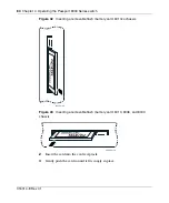
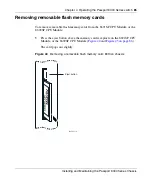
Page 83: ...h memory cards To install a removable flash memory card in a 8691SF CPU Module or 8692SF CPU Module 1 Position the card with the label facing to the left and the insert arrow pointing toward the card...

Page 84: ...ev 01 Figure 42 Inserting a removable flash memory card 8010co chassis Figure 43 Inserting a removable flash memory card 8010 8006 and 8003 chassis 2 Insert the card into the card receptacle 3 Gently...

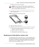
Page 85: ...ds To remove removable flash memory cards from the 8691SF CPU Module or the 8692SF CPU Module 1 Press the eject button above the memory card receptacle on the 8691SF CPU Module or the 8692SF CPU Modul...

Page 86: ...ur configuration you may want to write protect the memory card for backup purposes To change memory card protection 1 Remove the memory card from the 8000 Series chassis a Press the eject button above...

Page 87: ...nsert the card into the card receptacle c Gently push the card in until it fits snugly in place Replacing an air filter 8010co chassis only To maintain proper operation of the 8010co chassis you must...

Page 88: ...for the lower air filter can differ from that of the upper air filter because of its proximity to the floor You may want to replace both filters according to the shortest average Removing and inserti...

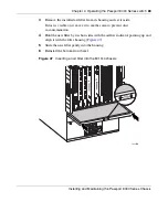
Page 89: ...ide If dust is visible on it move it to another area to prevent dust re contamination 4 Hold the new filter by its short sides with the airflow indicator pointing up and align it with the filter housi...

Page 90: ...vice such as a lamp to ensure that the power outlet is operational Verify that each power supply is turned on The Link Activity LED for a connected port is off or does not blink and you believe that t...

Page 91: ...m clock generation failure on its own circuitry Replace the module make sure that it is in the correct slot Note This LED has significance only for the module in slot 1 or slot 2 that provides the clo...

Page 92: ...fails to operate contact the Nortel Networks Technical Solutions Center for assistance Failure to get a login prompt from the Console port If you connect a terminal to the Console port of the 8691SF C...

Page 93: ...that has the sending pair attached to its receiving pair and vice versa If the two nodes are wired alike they both attempt to send data out on the same RJ 45 pins In such a case a straight through cab...

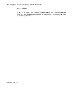
Page 94: ...ssport 8000 Series switch 316314 E Rev 01 GBIC cables Cables for the GBICs vary depending on the specific GBIC type For information about the cable requirements for GBICs see Installing SFP and XFP Tr...

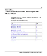
Page 95: ...e following topics This appendix includes the following topics Topic Page Model 8003AC power supply 96 Model 8004AC power supply 97 Model 8005AC power supply 98 Model 8004DC power supply 99 Model 8005...

Page 96: ...fications DC output power specifications AC input power specifications DC output power specifications Parameter Specifications Input voltage 100 240 VAC Input current 9 A Frequency 50 60 Hz Input VA 7...

Page 97: ...cifications DC output power specifications AC input power specifications DC output power specifications Parameter Specifications 100 240 VAC input voltage Input current 12 6 A Frequency range 50 60 Hz...

Page 98: ...ifications 100 120 VAC input voltage Specifications 200 240 VAC input voltage Input current 16 A 9 5 A Frequency range 50 60 Hz 50 60 Hz Input VA 1600 VA 1846 VA Input power consumption 1584 W 1828 W...

Page 99: ...the following topics DC input power specifications DC output power specifications DC input power specifications DC output power specifications Parameter Specifications Input voltage 48 VDC Input curr...

Page 100: ...C input power specifications DC output power specifications DC input power specifications DC output power specifications Parameter Specifications Input voltage 48 VDC Input current nominal 42 A Input...

Page 101: ...15 85 30 8616GTE 131 66 65 8616SXE 150 85 65 8624FXE 86 66 20 8630GBR 180 60 120 8648GTR 164 74 90 8648GTX 105 85 20 8660SDM 141 66 75 8672ATMM 96 66 30 8683XLR 168 78 90 8692SF 85 45 40 Fan tray asse...

Page 102: ...equals 1614 W Do not exceed either an individual voltage source or the combined power rating Table 16 Input power consumption sample configuration 8010 chassis Slot Module Total input power watts 3 3...

Page 103: ...le Table 18 shows that you would need two 8004DC power supplies to support the configuration shown in Table 16 The third 8004DC power supply provides redundancy Table 17 8004AC power supply example at...

Page 104: ...VAC you would need one 8005AC power supply to support the configuration shown in Table 19 The second 8005AC power supply provides redundancy Table 19 Input power consumption sample configuration 8006...

Page 105: ...AC power supply example at 200 240VAC Parameter Specifications Output power maximum 1462 W Individual 3 3 VDC power rating 508 W 3 385 V x 150 A Individual 12 VDC power rating 864 W 12 V x 72 A Table...

Page 106: ...Series Chassis 316314 E Rev 01 Note The 8001AC and 8002DC power supplies have not been tested with Passport 8600 modules released since Passport 8600 Release 3 7 Therefore Nortel Networks recommends...

Page 107: ...ow on page 108 International regulatory requirements on page 108 Physical specifications The following physical specifications apply to the 8010co chassis Network Equipment Building Standard The 8010c...

Page 108: ...irements Electromagnetic emissions next Electromagnetic immunity on page 109 Safety agency certification on page 109 Electromagnetic emissions The 8010co chassis conforms to the following electromagne...

Page 109: ...the following topics Physical specifications next Environmental specifications on page 110 International regulatory requirements on page 111 Canada ICES 003 Issue 2 Class A Europe EN 55022 1998 Class...

Page 110: ...5 cm Weight empty 85 lb 39 kg Weight fully loaded 225 lb 102 kg Cooling system Fan trays 2 per chassis Fans 8 per fan tray Thermal sensors 1 per fan tray Parameter Specification Operating temperature...

Page 111: ...The 8010 chassis conforms to the following electromagnetic emissions standards Electromagnetic immunity The 8010 chassis conforms to the following electromagnetic immunity standards Parameter Specific...

Page 112: ...fications on page 113 International regulatory requirements on page 113 Physical specifications The following physical specifications apply to the 8006 chassis Parameter Specification Global basis for...

Page 113: ...assis conforms to the following electromagnetic emissions standards Fans 6 per fan tray Thermal sensors 1 per fan tray Parameter Specification Operating temperature 0 C to 40 C 32 F to 104 F Storage t...

Page 114: ...EN 55022 1998 Class A EN 61000 3 2 A14 EN 61000 3 3 CE Marking Australia New Zealand AS NZS 3548 1995 Class A Japan VCCI V3 97 04 Class A Taiwan CNS 13438 Class A Parameter Specification Global basis...

Page 115: ...topics Physical specifications next Environmental specifications on page 116 International regulatory requirements on page 116 Physical specifications The following physical specifications apply to th...

Page 116: ...tromagnetic emissions next Electromagnetic immunity on page 117 Safety agency certification on page 117 Parameter Specification Operating temperature 0 C to 40 C 32 F to 104 F Storage temperature 25 C...

Page 117: ...Parameter Specification Global basis for certification CISPR 22 1997 Class A US FCC CFR47 Part 15 Subpart B Class A Canada ICES 003 Issue 2 Class A Europe EN 55022 1998 Class A EN 61000 3 2 A14 EN 610...

Page 118: ...118 Appendix A Technical specifications for the Passport 8000 Series Chassis 316314 E Rev 01...

Page 119: ...conventions text 20 crossover cable 93 customer support 21 D DTE DCE switch changing setting of 92 E electrical specifications 41 57 environmental specifications 41 58 equipment rack specifications 40...

Page 120: ...5 S shipment contents verifying 36 54 site requirements 40 57 software incompatibility 90 space requirements 40 57 specifications technical electrical 41 57 environmental 41 58 space 40 57 straight th...

Reviews: