


10-20
Page 37
2008-12-03
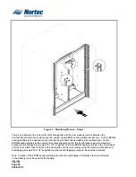
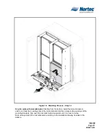
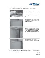
1.3.2 Mounting the MH Control Unit
Figure 5. Mounting the MH Control Unit
1. Fix the control panel to the wall using 4 x ¼” screws (not provided).
2. Connect the multi conductor control cables from the hydraulic unit to the corresponding
terminals in the control unit according the appropriate wiring diagram.
Important: all cables must be lead into the control unit via strain reliefs installed into the
openings in the bottom of the control panel housing.
3. MH Reflow models – Connect the power cable from the pump motor to the
corresponding terminals according to the appropriate wiring diagram.
Summary of Contents for MH Series
Page 1: ...2544832 A MH Series EVAPORATIVE HUMIDIFIER COOLER Installation Manual TM ...
Page 5: ...10 00 Page 1 2008 12 03 10 00 INTRODUCTION ...
Page 21: ...10 10 Page 17 2008 12 03 10 10 INSTALLATION ...
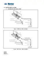
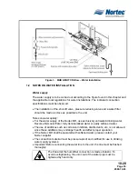
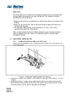
Page 37: ...10 20 Page 33 2008 12 03 10 20 PLUMBING ELECTRICAL INSTALLATION ...
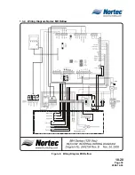
Page 42: ...10 20 Page 38 2008 12 03 1 3 3 Wiring Diagram Nortec MH Flow Figure 7 Wiring Diagram MH Flow ...
Page 44: ...10 20 Page 40 2008 12 03 THIS PAGE INTENTIONALLY LEFT BLANK ...
Page 45: ...10 30 Page 41 2008 12 03 10 30 OPERATION ...
Page 48: ...10 30 Page 44 2008 12 03 THIS PAGE INTENTIONALLY LEFT BLANK ...
Page 49: ...10 40 Page 45 2008 12 03 10 40 MAINTENANCE TROUBLESHOOTING ...