background image


ATOM Ku BUC/SSPA 

20W/25W/40W/50W 

Revision A 

908239 


19 

908239_rA - Operator Manual ATOM KU 20-

25-40-50W 


Each command response will have the following format: 

<CR><LF><msg><CR><LF>  

where msg is as described above and in the commands summary and example tables below.  Note that a 

response is enveloped by leading and trailing <CR><LF> characters. 


Table 2-3:  Commands Summary 

Command 

Param-Value 

Pairs 

Response Format 

(enveloping <CR><LF> characters not shown) 

getident 

None 

ok


pn

 <part#> 

swver

 <swver#> 

sn

 <serial#>  

where: 

<part#> = unit part number label 
<swver#> = software version label 
<serial#> = unit serial number label 

getstatus 

None 

ok


fault

 <fault#> 

fwdpwr

 <fwdpwr#> 

revpwr

 <revpwr#> 

temp

 <temp> 

where: 

<fault#> = fault flag, either 0 (no fault) or 1 (fault) .  

Use the getfaults command to determine the specific fault(s) 

<fwdpwr#> = forward power value, in dBm 
<revpwr#> = currently not used but reserved for reverse power 
<temp> = internal system temperature in degrees Celsius 

getfaults 

None 

ok mute 

<mute_flag>

 overTemp 

<temp_flag>

 pll 

<pll_flag> 

where: 

<mute_flag> = 0 (unit unmuted) or 1 (unit muted) 
<temp_flag> = 0 (temp ok) or 1 (error - over temp condition exists) 
<pll_flag> = 0 (pll ok) or 1 (error – pll loss of lock) 

resetfaults 

None 

ok 

setmute 

cmd

 (0|1) 

0 = unmute 
1 = mute 

ok 

M

UTE 

L

OGIC


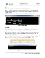
The unit will be muted when any of the following conditions exist: 

1.  A software mute command is issued through the serial interface. 

2.  A mute command/signal is issued through the discrete SHUTDOWN line (

Pin D: Shutdown (i.e. 

Mute Control)

. 

3.  A fault condition exists. 


Summary of Contents for ATOM 20W Ku-Band BUC

Page 1: ...Revision A 908239 1 908239_rA Operator Manual ATOM KU 20 25 40 50W ATOM Ku BUC SSPA 20W 25W 40W 50W Operator Manual Document Number 908239 Revision A Norsat International Inc 110 4020 Viking Way Richmond British Columbia Canada V6V 2L4 ...

Page 2: ...ewed and is believed to be entirely reliable Norsat International Inc hereinafter referred to as Norsat reserves the right however to modify any products herein to improve reliability function or design Norsat does not assume any liability arising out of the application or use of any product or circuit described herein Norsat does not convey any license under its patent rights or the rights of oth...

Page 3: ...on Norsat reserves the right to change this publication at any time without notice Copyright 2016 Norsat International Inc All rights reserved All materials contained in this user guide are the property of Norsat International Inc except as noted here below All materials in this user guide are protected by United States and international copyright laws The compilation of all content in this user g...

Page 4: ...h information necessary to operate the applicable system Technical Support is available from Norsat Norsat International Inc Attn Technical Support 110 4020 Viking Way Richmond BC Main 1 604 821 2800 Support 1 800 644 4562 sat support norsat com Customer Service Direct non technical questions and business related matters to Customer Support at the above number ...

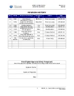
Page 5: ...5964 Update Address JLu Florence Leung 2014 09 05 1 3 6955 Added ESD Warning JLu Matt Battistel 2015 11 17 1 4 7478 Additional content for CE compliance HMei Matt Battistel 2016 05 24 1 5 7988 Corrected Pinout Table 2 1 SLei Thomas Pethick 2016 11 14 1 6 8108 Corrected RS 485 RS 232 grounding notes SLei Thomas Pethick 2017 01 05 A CN 000157 Document is applicable to 20W also SLei Frank Yang 2019 0...

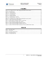
Page 6: ...CTION 2 2 MECHANICAL INSTALLATION 11 SECTION 2 3 J1 INPUT 12 BUC 12 SSPA 12 SECTION 2 4 J2 MONITOR AND CONTROL INTERFACE 12 Pin Outs 12 Pin D Shutdown i e Mute Control 13 Pin G GND 14 Pin A B C J RS 485 14 Pin E F RS 232 14 SECTION 2 5 SERIAL PORT SOFTWARE INTERFACE 15 Controller Responses 15 Message Definitions 16 Command Response 18 Mute Logic 19 SECTION 2 6 J3 DC POWER 20 Connector Type 20 J3 C...

Page 7: ...te unit 18 Figure 2 9 J3 Connector Pin Out Viewed Looking at SSPA BUC from the Outside 21 Figure A 1 20W and 25W Interconnect Locations 24 Figure A 2 20W and 25W KU SSPA BUC Assembly without Fans 25 Figure A 3 20W and 25W Base Plate Mounting Locations 26 Figure A 4 40W and 50W KU SSPA BUC Assembly with Fans 27 Figure A 5 40W and 50W KU SSPA BUC Assembly without Fans 28 Figure A 6 40W and 50W KU SS...

Page 8: ...U025 ATOMSKU040 ATOMSKU050 ATOMBKU020 ATOMBKU025 ATOMBKU040 ATOMBKU050 BUC BLOCK UP CONVERTER AND AMPLIFIER If this unit is a BUC this unit converts IF to RF in the KU range for the frequencies specified in the original configuration of this unit and amplifies the power to the specified power SSPA SOLID STATE POWER AMPLIFIER If this unit is an SSPA only this unit amplifies the input signal to the ...

Page 9: ...tput type to SMA TNC or N Type connectors Please contact Norsat for more information ELECTRICAL INTERFACE M C Connector ten pin connector used to interface to a host computer See Chapter 2 for detailed description of pin outs Power Connector four pin connector used to provide power to unit See Chapter 2 for detailed description of pin outs FUSE On units equipped with the EMC EMI filter option ther...

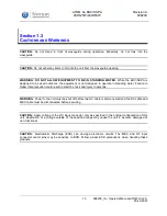
Page 10: ...in standing water Failure to follow this precaution could result in electric shock and injury to persons WARNING Power to the unit must be shut off before the DC cable is disconnected and the DC cable and M C cable must be disconnected before servicing CAUTION Apply voltage to the DC input connector only as specified in the original configuration of this unit Application of a voltage outside of th...

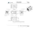
Page 11: ...h must be supplied by the end user There are a number of 6 32 UNC threaded holes on each face of the main housing to facilitate mounting in many different applications and in any orientation please refer to Appendix A for exact mounting hole locations The preferred mounting scheme is to fix the ATOM to the larger assembly using at least four mounting points on each of two opposite sides of the uni...

Page 12: ...l on board sensors are read through this interface including forward power monitoring In default mute configuration refer to section Pin D Shutdown i e Mute Control use of this connection is optional PIN OUTS The monitor and control interface is a ten pin connector CAUTION EXTREME CARE MUST BE USED WITH THIS CONNECTOR TO AVOID ELECTRO STATIC DISCHARGE ESD Many units have been damaged by improper E...

Page 13: ...RS 485 Host computer RX signal signal out of unit K Reserved Leave unconnected open circuited Figure 2 1 J2 Connector Pin Out Viewed Looking at SSPA BUC from the Outside PIN D SHUTDOWN I E MUTE CONTROL This pin implements the shutdown or mute function and the user should apply Ground to this pin to mute the amplifier When muted the unit power transistors are turned off reducing power consumption a...

Page 14: ...s on the outside of the aluminum case PIN A B C J RS 485 These four pins form a standard RS 485 port with RX RX TX TX Use Pin G as the ground reference for this port TX and TX are the differential pair which carries a signal from the host computer to the unit RX and RX are the differential pair which carries a signal from the unit to the host computer Ensure these are connected to the host compute...

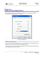
Page 15: ...ndard Terminal program with setup parameters as shown in Figure 2 2 Figure 2 2 Setup Serial Port CONTROLLER RESPONSES The unit will only generate messages in response to a command Each command received will result in a single message reply which may simply be an Acknowledge message In general command responses are returned immediately though the precise command response delay varies slightly based...

Page 16: ...s This command instructs the unit to respond with fault flag forward power and temperature Note reverse power revpwr in the response is a future enhancement and is not currently supported A 0 after fault indicates no faults A 1 indicates a fault Use command getfaults to determine what fault exists Power is in dBm Temperature is in degrees C The temperature scale is from 55 to 150 C with approximat...

Page 17: ...an error Since the unit can be commanded into mute state without a fault the resetfaults command will not clear a mute fault in this situation The temperature sensor has a trip point above which a fault is triggered and a reset point below which a fault is automatically cleared The reset point is set below the trip point to provide hysteresis See Table 2 2 for Trip and Reset Points The resetfaults...

Page 18: ...d setmute mute unit Figure 2 8 Command setmute unmute unit COMMAND RESPONSE The CLI operates on a command response format Each time a command is entered a response will be displayed If a command executed correctly an ok along with potential parameters and values will be displayed Otherwise err will be displayed along with a description of the error The potential errors that may be displayed are In...

Page 19: ...wr revpwr revpwr temp temp where fault fault flag either 0 no fault or 1 fault Use the getfaults command to determine the specific fault s fwdpwr forward power value in dBm revpwr currently not used but reserved for reverse power temp internal system temperature in degrees Celsius getfaults None ok mute mute_flag overTemp temp_flag pll pll_flag where mute_flag 0 unit unmuted or 1 unit muted temp_f...

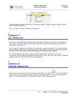
Page 20: ... limit between 20A and 23A The DC power cable must be capable of safely carrying at least 10A continuous for 25W ATOMs and 20A continuous for 40W 50W and low voltage 25W ATOMs Note that the power supply connection should not be made with the power live The unit should not be powered on until all input and output connections have been made CONNECTOR TYPE The J3 connector is a four pin cannon type c...

Page 21: ...OM Ku BUC SSPA 20W 25W 40W 50W Revision A 908239 21 908239_rA Operator Manual ATOM KU 20 25 40 50W J3 CONNECTOR PIN OUTS Figure 2 9 J3 Connector Pin Out Viewed Looking at SSPA BUC from the Outside A B C D ...

Page 22: ...tions after bolting the waveguide to waveguide connection it is recommended to add RTV silicone compound as a sealant around the entire perimeter of the joint where the flanges meet This will provide extra protection against water ingress at the flange to flange interface The unit is supplied with two screw lengths four 6 32x3 8 and four 6 32x7 16 it is the users responsibility to ensure that the ...

Page 23: ...application Use a high quality M C cable that s shielded grounded at both ends and not longer than necessary for the application Place two ferrite clamps such as Laird Signal Integrity Products 28A3851 0A2 on the DC cable closest to the ATOM Make sure the GND stud is connected according to national and local electrical codes If a serial to USB converter is used its case should be locally grounded ...

Page 24: ...ATOM Ku BUC SSPA 20W 25W 40W 50W Revision A 908239 24 908239_rA Operator Manual ATOM KU 20 25 40 50W Appendix A Mechanical Drawings DRAWINGS 20W AND 25W Figure A 1 20W and 25W Interconnect Locations ...

Page 25: ...ATOM Ku BUC SSPA 20W 25W 40W 50W Revision A 908239 25 908239_rA Operator Manual ATOM KU 20 25 40 50W Figure A 2 20W and 25W KU SSPA BUC Assembly without Fans ...

Page 26: ...ATOM Ku BUC SSPA 20W 25W 40W 50W Revision A 908239 26 908239_rA Operator Manual ATOM KU 20 25 40 50W Figure A 3 20W and 25W Base Plate Mounting Locations ...

Page 27: ...ATOM Ku BUC SSPA 20W 25W 40W 50W Revision A 908239 27 908239_rA Operator Manual ATOM KU 20 25 40 50W DRAWINGS 40W AND 50W Figure A 4 40W and 50W KU SSPA BUC Assembly with Fans ...

Page 28: ...ATOM Ku BUC SSPA 20W 25W 40W 50W Revision A 908239 28 908239_rA Operator Manual ATOM KU 20 25 40 50W Figure A 5 40W and 50W KU SSPA BUC Assembly without Fans ...

Page 29: ...ATOM Ku BUC SSPA 20W 25W 40W 50W Revision A 908239 29 908239_rA Operator Manual ATOM KU 20 25 40 50W Figure A 6 40W and 50W KU SSPA BUC Assembly with Fans and EMC EMI Filter Option ...

Page 30: ...inition BUC Block Upconverter AMP Amplifier C Celsius dBm Decibel milliwatts DC EMC Direct Current Electromagnetic Compatibility ESD Electrostatic Discharge freq Frequency GHz Gigahertz GND Ground IF Intermediate Frequency kHz kilohertz M C Monitor and Control MHz Megahertz mm Millimeter N A Not Applicable ppm Pulses per minute RF Radio Frequency RX Receive SSPA Solid State Power Amplifier TX Tran...

Reviews: