CONFIDENTIAL AND PROPRIETARY
©Norsat International Incorporated (“Norsat”) All Rights
Reserved
2021-02-16 INS001201 Rev B
16
Sample 1
0V =
Unmute
Pull-Up
0V
Unmuted
5V
Muted
Floating
Muted
Sample 2
5V =
Unmute
Pull-
Down
0V
Muted
5V
Unmuted
Floating
Muted
Sample 3
5V =
Unmute
Pull-Up
0V
Muted
5V
Unmuted
Floating
Unmuted
Note that the ATOM mute state can also be controlled through the M&C interface. The software
mute setting takes priority over the hardware pin. Refer to
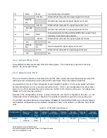
2.4.4 RS-485 Port: Pins A, B, C, J
These four pins form a standard RS-485 port, with RX+, RX-, TX+, TX-. Use Pin G as the ground reference
for this port.
TX+ and TX- are the differential pair which carries a signal from the host computer to the unit. RX+ and RX-
are the differential pair which carries a signal from the unit to the host computer. Ensure these are
connected to the host computer RS-485 port accordingly.
•
A
TX- (RS-485)
Host computer TX- signal (signal into unit)
•
B
TX+ (RS-485)
Host computer TX+ signal (signal into unit)
•
C
RX+ (RS-485)
Host computer RX+ signal (signal out of unit)
•
J
RX- (RS-485)
Host computer RX- signal (signal out of unit)
2.4.5 RS-232 Port: Pins E, F, & G
These pins form a standard RS-232 serial port. Pin F carries a signal from the host computer to the unit
and Pin E carries a signal from the unit to the host computer. Pin G must be connected to the ground pin
on the host computer.
2.4.6 Ethernet Interface: Pins E, F, H, & K
These four pins form a standard 10/100Mbps Ethernet link. Table 2-5 and Figure 2-9 summarize how to
construct an Ethernet M&C cable to access the web interface.
Table 2-5: Ethernet Cable Pinout
ATOM
Connector
Twisted Pair
Cable
RJ-45
Connector
Description
F
Wht/Grn
1
Ethernet host computer Tx+ signal (signal into unit)


