background image

CONFIDENTIAL AND PROPRIETARY 


©Norsat International Incorporated (“Norsat”) All Rights 

Reserved 

2021-02-16 INS001201 Rev B


21


Table 2-7:  Commands Summary 

Command 

Param-

Value 

Pairs 

Response Format 

(enveloping <CR><LF> characters not shown) 

getident 

None 

ok


pn

 <part#> 

swver

 <swver#> 

sn

 <serial#>  

where: 

<part#> = unit part number label 
<swver#> = software version label 
<serial#> = unit serial number label 

getstatus 

None 

ok


fault

 <fault#> 

fwdpwr

 <fwdpwr#> 

revpwr

 <revpwr#> 

temp

 <temp> 

where: 

<fault#> = fault flag, either 0 (no fault) or 1 (fault) .  

Use the getfaults command to determine the specific 
fault(s) 

<fwdpwr#> = forward power value, in dBm 
<revpwr#> = currently not used but reserved for reverse power 
<temp> = internal system temperature in degrees Celsius 

getfaults 

None 

ok mute 

<mute_flag>

 overTemp 

<temp_flag>

 pll 

<pll_flag> 

where: 

<mute_flag> = 0 (unit unmuted) or 1 (unit muted) 
<temp_flag> = 0 (temp ok) or 1 (error - over temp condition exists) 
<pll_flag> = 0 (pll ok) or 1 (error 

 pll loss of lock) 

resetfaults 

None 

ok 

setmute 

cmd

 (0|1) 

0 = unmute 
1 = mute 

ok 


2.5.4  Mute Logic 


The unit will be muted when any of the following conditions exist: 

1.  A software mute command is issued through the serial interface. 

2.  A mute command/signal is issued through the discrete SHUTDOWN line (

Pin D: Shutdown (i.e. 

Mute Control)

3.  A fault condition exists. 


Summary of Contents for ATOM-100060

Page 1: ...1 USER MANUAL ATOM Ka 25 40W 50W BUC SSPA ...

Page 2: ...s to improve reliability function or design Norsat does not assume any liability arising out of the application or use of any product or circuit described herein Norsat does not convey any license under its patent rights or the rights of others Technical Support This manual provides engineers with information necessary to operate the applicable system Technical support is available from Norsat Nor...

Page 3: ...nd Terminal 12 2 3 J3 DC Power 12 2 3 1 Connector Type 12 2 3 2 DC Unit J3 Connector Pinouts 13 2 4 J2 Monitor and Control Interface 13 2 4 1 Monitor and Control Interface Pinout 14 2 4 2 Ground Pin s Pin G 15 2 4 3 Mute Control Pin D 15 2 4 4 RS 485 Port Pins A B C J 16 2 4 5 RS 232 Port Pins E F G 16 2 4 6 Ethernet Interface Pins E F H K 16 2 5 Serial Port Software Interface 17 2 5 1 Controller ...

Page 4: ...ound Connection 24 2 9 Fault Indicator LED 24 2 9 1 Description of Operation 24 2 9 2 Modes of Operation 24 2 9 3 Starting with No Faults Status 24 2 9 4 Fault and No Faults 24 3 Misc Info 24 3 1 ATOM Installation 24 3 1 1 Mounting 24 3 1 2 Outdoor Use 25 3 2 Fans Baseplate Cooling 25 3 3 Accessories 25 3 4 General Specifications 25 3 5 Standard Warranty 26 Appendix A Mechanical Drawings 27 Append...

Page 5: ...ATOM Ka 25W 40W units 11 Figure 2 6 Standard Waveguide Output for ATOM Ka 50W units 11 Figure 2 7 DC Unit J3 Connector Pinout 13 Figure 2 8 J2 M C Connector Pin Arrangement 14 Figure 2 9 RJ 45 Plug Pinout 17 Figure 2 10 Setup Serial Port 18 Figure 2 11 Command getident 18 Figure 2 12 Command getstatus 19 Figure 2 13 Command getfaults 19 Figure 2 14 Command resetfaults 20 Figure 2 15 Command setmut...

Page 6: ... 7 Table 2 1 DC Unit J3 Connector Pinout 13 Table 2 2 M C Interface Options 14 Table 2 3 J2 Pinouts for ATOM Configurations 14 Table 2 4 ATOM Mute Control Behavior 15 Table 2 5 Ethernet Cable Pinout 16 Table 2 6 Fault Trip and Reset Points 19 Table 2 7 Commands Summary 21 Table 3 1 General 25 50W ATOM Specifications 25 Table B 3 1 Acronyms and Abbreviations 31 ...

Page 7: ...30 0 31 0 GHz Dual Band 29 0 30 0 GHz 30 0 31 0 GHz or Specific Bands This also includes the ATOM 100060 Ka 40W BUC as specified 1 1 1 SSPA Solid State Power Amplifier If this unit is a SSPA the RF input signal is amplified to the specified power 1 1 2 BUC Block Up Converter and Amplifier If this unit is a BUC the IF input signal is upconverted to Ka Band RF frequencies and then amplified to the s...

Page 8: ... prior to powering on the ATOM W A R N I N G RF Radiation Hazard The ATOM emits high power RF energy which is harmful to the human body Do not operate ATOM unless the RF output flange is either terminated in an RF load 100W min or connected to the feed of a terminal Do not obstruct the RF output or feed output with any body part W A R N I N G Do not allow equipment to be standing in water While th...

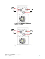
Page 9: ...the output side The interface for these connectors is detailed in this document On the input side there are the following connectors J1 IF or RF Input N Type Jack for BUC K Type Jack for SSPA J2 Ten pin circular connector for M C J3 Four pin circular DC power connector J6 Ground terminal Figure 2 1 Input Connections for ATOM Ka 25W 40W BUC Unit N Type Jack Shown J3 Figure 2 2 Input Connections for...

Page 10: ...t International Incorporated Norsat All Rights Reserved 2021 02 16 INS001201 Rev B 10 Figure 2 3 Input Connections for ATOM Ka 50W BUC Unit N Type Jack Shown J3 J1 J6 J2 Figure 2 4 Input Connections for ATOM Ka 50W SSPA Unit J2 J6 J3 J1 ...

Page 11: ...ated Norsat All Rights Reserved 2021 02 16 INS001201 Rev B 11 On the output side there is one connector J4 WR28 waveguide RF output J4 Figure 2 6 Standard Waveguide Output for ATOM Ka 50W units J4 Figure 2 5 Standard Waveguide Output for ATOM Ka 25W 40W units ...

Page 12: ... a mating connector for the power interface Refer to specific configuration of the unit for the exact voltage range Power is supplied through a four pin type cylindrical connector Two pins are used to deliver the positive connection and two pins are used for the negative connection in order to reduce resistance The negative connection is internally connected to case ground The negative power conne...

Page 13: ...ternally It is recommended to apply the supply voltage evenly to both pairs of pins to evenly share the current among both sets of wires pins The internal capacitance between the V and V terminals is approximately 120 microfarads 2 4 J2 Monitor and Control Interface The M C interface is used to control the unit with a host computer All on board sensors are accessed through this interface Use of th...

Page 14: ...be used to add options to the plug such as right angle stress relief clamp metal color finish etc Please contact the connector manufacturer for more information and or refer to Amphenol catalog 12 070 Figure 2 8 J2 M C Connector Pin Arrangement Table 2 3 summarizes the various pinout options for the 25 50W ATOM Ka Note that the pin function varies according to the M C interface option that the ATO...

Page 15: ...er transistors are turned off reducing power consumption and providing an RF output noise close to the thermal noise floor The operation of this pin is fully configurable through the M C Interface Pin D can be biased with either an internal Pull Down to 0V or an internal Pull Up to 4V Pin D is also configurable to be either active high 3 5V on Pin D will mute the unit or active low 0 0 8V on Pin D...

Page 16: ...h carries a signal from the unit to the host computer Ensure these are connected to the host computer RS 485 port accordingly A TX RS 485 Host computer TX signal signal into unit B TX RS 485 Host computer TX signal signal into unit C RX RS 485 Host computer RX signal signal out of unit J RX RS 485 Host computer RX signal signal out of unit 2 4 5 RS 232 Port Pins E F G These pins form a standard RS...

Page 17: ...o unit E Wht Org 3 Ethernet host computer Rx signal signal out of unit Blu 4 Wht Blu 5 H Org 6 Ethernet host computer Rx signal signal out of unit Wht Brn 7 Brn 8 Figure 2 9 RJ 45 Plug Pinout 2 5 Serial Port Software Interface Communications to and from the serial interface is character based Use any standard Terminal program with setup parameters as shown in Figure 2 10 ...

Page 18: ...s are returned immediately though the precise command response delay varies slightly based on the specific command 2 5 2 Message Definitions getident This command returns the part number software revision and serial number of the unit Figure 2 11 Command getident getstatus This command instructs the unit to respond with fault flag forward power and temperature Note reverse power revpwr in the resp...

Page 19: ...rs faults under certain conditions Note that the mute fault code indicates muted state not necessarily an error Since the unit can be commanded into mute state without a fault the resetfaults command will not clear a mute fault in this situation The temperature sensor has a trip point above which a fault is triggered and a reset point below which a fault is automatically cleared The reset point is...

Page 20: ...perates on a command response format Each time a command is entered a response will be displayed If a command executed correctly an ok along with potential parameters and values will be displayed Otherwise err will be displayed along with a description of the error The potential errors that may be displayed are Invalid Command The command was not recognized Invalid Parameter The parameter was not ...

Page 21: ...determine the specific fault s fwdpwr forward power value in dBm revpwr currently not used but reserved for reverse power temp internal system temperature in degrees Celsius getfaults None ok mute mute_flag overTemp temp_flag pll pll_flag where mute_flag 0 unit unmuted or 1 unit muted temp_flag 0 temp ok or 1 error over temp condition exists pll_flag 0 pll ok or 1 error pll loss of lock resetfault...

Page 22: ...accessed through any web browser such as Mozilla Firefox recommended Google Chrome Opera or Internet Explorer To access the web interface launch the web browser and type in the IP Address for the ATOM http 192 168 77 30 index html A simplified version of the ATOM Control software will load in the browser window 2 6 3 Using ATOMControl Web Interface The Web Interface use and operation is identical ...

Page 23: ...to the desired setting Ethernet Method alternate method 5 Connect the ATOM s Ethernet port directly to a computer running Microsoft Windows and power on the ATOM 6 Disable any wireless connections if present 7 Launch a command prompt window Start Run cmd 8 Type in the following command and press the carriage return key Tx arp a cr 9 A list of all Ethernet devices connected to the computer will be ...

Page 24: ...FAULT and NO FAULTS 2 9 3 Starting with No Faults Status The Status LED will flash once for a lapse of approximately one second every time the power of the device in recycled to OFF and set back to ON If no fault is detected in the device at the Power Up the led will go to OFF afterwards settling in that state 2 9 4 Fault and No Faults In the event of a PLL Fault or an Over Temperature Fault the S...

Page 25: ...ensure there is adequate cooling to remove heat and prevent the unit from overheating The ATOM is also available with a flat plate in place of the radiators and fans It is the user s responsibility to ensure that the plate the unit is mounted to is capable of rejecting any heat produced by the unit Please contact Norsat for cooling requirement specifications 3 3 Accessories Each ATOM unit ships wi...

Page 26: ...dependent Configuration dependent 3 5 Standard Warranty Norsat International Incorporated warrants that its equipment shall be free from defects in material or workmanship for a period of one 1 year from the ship date unless otherwise stated in the Offer Terms and Conditions The warranty does not cover units that have been damaged through improper use or physical damage e g dropped units been modi...

Page 27: ...CONFIDENTIAL AND PROPRIETARY Norsat International Incorporated Norsat All Rights Reserved 2021 02 16 INS001201 Rev B 27 Appendix A Mechanical Drawings Figure A 3 1 25W 40W Ka BUC SSPA Fan Cooled ...

Page 28: ...CONFIDENTIAL AND PROPRIETARY Norsat International Incorporated Norsat All Rights Reserved 2021 02 16 INS001201 Rev B 28 Figure A 3 2 25W 40W Ka BUC SSPA Baseplate Cooled ...

Page 29: ...CONFIDENTIAL AND PROPRIETARY Norsat International Incorporated Norsat All Rights Reserved 2021 02 16 INS001201 Rev B 29 Figure A 3 3 50W Ka BUC SSPA Fan Cooled ...

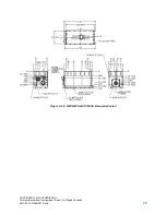
Page 30: ...orsat International Incorporated Norsat All Rights Reserved 2021 02 16 INS001201 Rev B 30 Figure A 3 4 50W Ka BUC SSPA Baseplate Cooled Note 1 N Connector Input Shown For SSPA option the N Connector will be replaced with K Connector ...

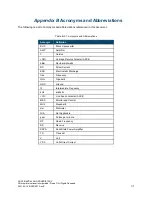
Page 31: ...s Acronym Definition BUC Block Upconverter AMP Amplifier C Celsius CR Carriage Return character ASCII dBm Decibel milliwatts DC Direct Current ESD Electrostatic Discharge freq Frequency GHz Gigahertz GND Ground IF Intermediate Frequency kHz kilohertz LF Line Feed character ASCII M C Monitor and Control MHz Megahertz mm Millimeter N A Not Applicable ppm Pulses per minute RF Radio Frequency RX Recei...

Page 32: ...s military organizations health care providers and Fortune 1000 companies ABOUT NORSAT Norsat International Inc founded in 1977 is a leading provider of innovative communication solutions that enable the transmission of data audio and video for remote and challenging applications Norsat s products and services include customizable satellite components portable satellite terminals maritime solution...

Reviews: