Nordyne R4GD 024K045 Installation Instructions Manual Download Page 12

12

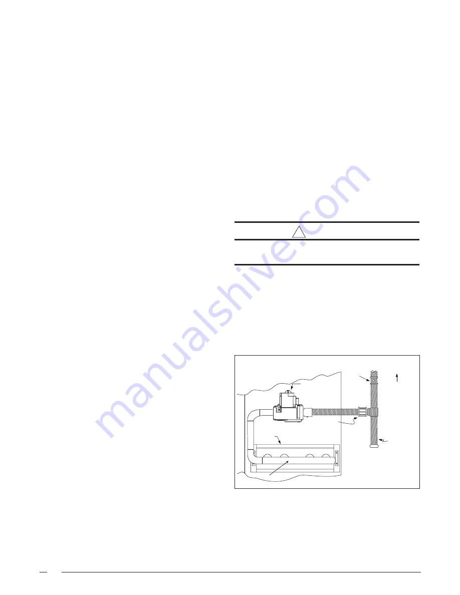
Figure 7.  Typical Right Side Entry

Gas Service Connection.

Ground Joint
Union

Dripleg

Shut-Off Valve

with 1/8 NPT

plugged tap

Burner
Assembly

Manifold

Some utilities

require Shut-Off

Valve to be

4 to 5 feet

above floor

Automatic Gas

Valve (with manual

shut-off)

It is recommended that the outlet duct be provided with a
removable access panel. This opening should be accessible
when the unit is installed in service and shall be of a size
such that the smoke or reflected light may be observed
inside the casing to indicate the presence of leaks in the
heat exchanger.  The cover for the opening shall be
attached in such a manner as to prevent leaks.

If outside air is utilized as return air to the unit for ventilation
or to improve indoor air quality, the system must be
designed so that the return air to the unit is not less than
50°F (10°C) during heating operation. If a combination of
indoor and outdoor air is used, the ducts and damper
system must be designed so that the return air supply to
the furnace is equal to the return air supply under normal,
indoor return air applications.

Unconditioned Spaces — All ductwork passing through
unconditioned space must be properly insulated to minimize
duct losses and prevent condensation.  Use insulation
with an outer vapor barrier.  Refer to local codes for
insulation material requirements.

Acoustical Ductwork — Certain installations may require
the use of acoustical lining inside the supply ductwork.
Acoustical insulation must be in accordance with the
current revision of the Sheet Metal and Air Conditioning
Contractors National Association (SMACNA) application
standard for duct liners.  Duct lining must be UL classified
batts or blankets with a fire hazard classification of FHC-
25/50 or less.  Fiber ductwork may be used in place of
internal duct liners if the fiber ductwork is in accordance
with the current revision of the SMACNA construction
standard on fibrous glass ducts.  Fibrous ductwork and
internal acoustical lining must be NFPA Class 1 air ducts
when tested per UL Standard 181 for Class 1 ducts.

Horizontal to Down flow Conversion — The unit is
shipped ready for horizontal duct connections.  If down
flow ducts are required, the unit must be converted following
the steps below for both the supply and return ducts.

1. Locate the duct cap inside the duct openings and

remove the screw holding it in place.

2. Lift the cap out of the unit.  The cap can be pushed

up from the bottom by reaching through the fork slot.

3. Cover the horizontal duct opening with the cap.  The

insulation will be on the indoor side.

4. Fasten the cover with screws and seal to prevent air

leakage.

GAS SUPPLY AND PIPING

This unit has right side gas entry.  A typical gas service
hookup is shown in Figure 7. When making the gas
connection, provide clearance between the gas supply
line and the entry hole in the unit’s casing to avoid
unwanted noise and/or damage to the unit.

All gas piping must be installed in compliance with local
codes and utility regulations. Some local regulations require
the installation of a manual main shut-off valve and ground
joint union external to the unit.  The shut-off valve should
be readily accessible for service and/or emergency use.
Consult the local utility or gas supplier for additional
requirements regarding placement of the manual main gas
shut-off. In the absence of local codes the gas line
installation must comply with the latest edition of the
National Fuel Gas Code ANSI Z223.1 or CAN/CGA B149
Installation Codes.

!

CAUTION:

Do not use matches, lighters, candles or other
sources of open flame to check for gas leaks.

A 1/8 inch NPT plugged tap must be installed in the gas line
immediately upstream of the gas supply connection to the
furnace for use when measuring the gas supply pressure.
The plug should be readily accessible for service use. A
drip leg should be installed in the pipe run to the unit. Table
4
 lists gas flow capacities for standard pipe sizes as a
function of length in typical applications based on nominal
pressure drop in the line.

Summary of Contents for R4GD 024K045

Page 1: ...ncy or the gas suppli er These instructions are primarily intended to assist qualified individuals experienced in the proper installation of this appliance Some local codes require licensed installati...

Page 2: ...2...

Page 3: ...neral 14 LineVoltage 14 Electrical Data Table 15 BlowerSpeed 15 RoomThermostat 16 SYSTEM CHECK 16 Pre Start Check List 16 WIRINGDIAGRAMS 18 START UPPROCEDURE 16 AirCirculation 16 Short Cycle Protectio...

Page 4: ...avebeensecurelypackaged atthepointofshipment Afterunpackingtheunit carefully inspect it for apparent and concealed damage Claims for damage should be filed with the carrier by the consignee Requiremen...

Page 5: ...upply Entry Low Voltage Entry Gas Supply Entry 16 6 24 6 31 0 2 9 1 8 4 0 12 45 12 45 4 0 55 8 8 75 Horizontal Supply Duct Opening Horizontal Return Duct Opening 4 0 1 75 9 75 24 75 16 0 Condensing Co...

Page 6: ...39 0 35 3 024K072 435 445 26 0 26 5 39 0 35 3 030K045 430 440 26 5 26 5 39 0 35 3 030K072 440 450 26 0 26 5 39 0 35 3 036K072 470 480 26 5 26 5 39 0 35 3 036K096 485 495 26 0 26 5 39 0 35 3 042K072 50...

Page 7: ...re being replaced condensation Do not install the unit such that exhaust from the vent termination is directed into window wells stairwells under decks or in alcoves or similarly recessed areas The ve...

Page 8: ...D E Blower Control Duct Coil Panel A Panel B Panel C End D Top E 024 045 45 000 36 36 1 36 36 024 072 72 000 36 36 1 36 36 030 045 45 000 36 36 1 36 36 030 072 72 000 36 36 1 36 36 036 072 72 000 36...

Page 9: ...e combustible material on or against the unit cabinet Do not place combustible materials including gasoline and any other flammable vapors and liquids in the vicinity of the unit Figure 4 Condensate D...

Page 10: ...exposure to contaminated combustion air will result in safety and performance related problems CIRCULATING AIR SUPPLY WARNING Products of combustion must not be allowed to enter the return air ductwor...

Page 11: ...5 1520 1465 1405 1340 1280 41 1235 42 T1 1020 68 940 74 860 800 740 680 615 570 T2 1185 59 1110 63 1035 67 980 925 875 820 785 T3 1410 49 1330 52 1250 56 1195 58 1140 61 1085 64 1030 67 975 71 T4 1525...

Page 12: ...truction standard on fibrous glass ducts Fibrous ductwork and internal acoustical lining must be NFPA Class 1 air ducts when tested per UL Standard 181 for Class 1 ducts Horizontal to Down flow Conver...

Page 13: ...use fire explosion property damage carbon monoxide poisoning personal injury or death GAS AND HIGH ALTITUDE CONVERSIONS Conversion conversion of this unit must be performed by qualified service person...

Page 14: ...WARNING To avoid the risk of electrical shock personal injury or death disconnect all electrical power to the unit before performing any maintenance or service The unit may have more than one electric...

Page 15: ...le 7 or on the unit rating label and according to the National Electric Code and applicable local codes Provide power supply or supplies for the unit in accordance with the unit wiring diagram and the...

Page 16: ...ns at Note Ifthesamespeedisrequiredforbothheatingand cooling remove either the red or orange wire from the blower motor Next obtain the jumper wire from the homeownerspacketandconnectittotheblowerrela...

Page 17: ...peed Motors Green Gray Black Yellow Blue 1 2 3 4 5 6 7 8 9 R C Y G W X Y1 R G W1 Gas Valve Typical Wiring Field Supplied for 1 Stage Cool 1 Stage Heat Typical Wiring Field Supplied for 2 Stage Cool 1...

Page 18: ...Low Flame Sensor Signal Continuous Flash Flame Present On 1 1 2 2 FLAME ROLL OUT SWICH LIMIT SWITCH TO THERMOSAT Y2 Y C W1 G R PRESSURE SWITCH GROUND R C Y G W NEUTRALS EAC HUM XFMR L1 EAC COOL HEAT...

Page 19: ...t must not exceed that on the data label less 4 for each 1 000 ft Follow the procedure below to determine the firing rate 1 Shut off all other gas fired appliances 2 Start the unit in heating mode and...

Page 20: ...est setting 2 Turn off all electrical power to the appliance if service is to be performed 3 Remove the control access door panel upper door if two door model 4 Move the gas control knob clockwise to...

Page 21: ...ntrollocatedintheunitcontrolbox Thewiring diagram on the unit and in Figure 10 show the speed taps for adjusting motor speed Refer to the Blower Speed Section of this installation instruction for more...

Page 22: ...d environmentally responsiblerefrigeranthandlingprocedures WARNING The gas electric units are shipped fully charged and ready for installation When a system is installed according to these instruction...

Page 23: ...g space can create potentially hazardous conditions including carbon monoxide poisoning that could result in personal injury or death Cleaning of Heat Exchanger If the heat exchanger must be cleaned d...

Page 24: ...clean them if necessary with a soft wire brush and or the nozzle of a vacuum cleaner BE EXTREMELY CAREFUL NOT TO DAMAGE THE IGNITOR WHILE CLEANING THE BURNER 10 Replaceallthepartsinreverseorderfromwhi...

Page 25: ...he warm up interval is increased by 3 seconds on the next try And if successful it remains there Min and max warm up time limits are set at 6 and 54 seconds respectively 6 Theflamemustbeproventhrought...

Page 26: ...______ Has the Owner s Information been reviewed with the homeowner _________________________________ Has the Literature Package been left with the homeowner _________________________________ Minimum...

Page 27: ...27...

Page 28: ...Replaces7085310 Specifications and illustrations subject to change without notice and without incurring obligations PrintedinU S A 03 06 O Fallon MO INSTALLER PLEASE LEAVE THESE INSTALLATION INSTRUCT...

Reviews: