L (mm)
L (ft)
A1 (mm)
Industria IP65 14W
653 mm
2
390 mm
Industria IP65 23W 1263 mm
4
900 mm
Industria IP65 29W 1563 mm
5
1000 mm
Fig 1
2
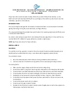
These instructions should be read carefully and retained after installation by the end user for
future reference and maintenance.
These instructions should be used to aid installation of the following products:
TRLED12 / TRLED14 / TRLED15 / TRLED16 / TRLED22 / TRLED24 / TRLED25 / TRLED26
GENERAL INSTRUCTIONS
SAFETY
INSTALLATION
• Installation of this luminaire should only be carried out by a qualified electrician or competent
person to the latest Building and current IEE Wiring Regulations (BS7671)
• Please isolate mains prior to installation/maintenance
• Check the total load on the circuit (including when this luminaire and LED load is fitted) does not
exceed the rating of the circuit cable, fuse or circuit breaker
• Please note the IP (Ingress of Protection) rating of this product when deciding the location for
installation
• This product is Class I and must be earthed
• This product is IP65 rated
• This product is non-dimmable
Note: Outdoor electrical installations should be protected by an earth leakage circuit breaker such as
a residual current device (RCD)
Note: If this luminaire is being used in conjunction with external PIR or sensors, please confirm with
the manufacturer of the sensors that they are compatible with LED luminaires
• Provide power to the required point of installation
• Important: Subject to the surface foundation material, ensure the correct fixings are used. If
installed outside, the mains cable should be connected into a suitable IP rated junction box
• Referring to Fig 1, using the mounting brackets as a template, mark the location of the fixing holes.
Drill the fixing holes ensuring not to infringe with any joists, gas/water pipes, or electrical cables
that may be hidden behind the surface
TRLEDxx
GENERAL INSTRUCTIONS
These instructions should be read carefully and retained after installation by the end user for future reference and
maintenance.
These instructions should be used to aid installation of the following products:
TRLED12 / TRLED14 / TRLED15 / TRLED16 / TRLED22 / TRLED24 / TRLED25 / TRLED26
SAFETY
•
Installation of this luminaire should only be carried out by a qualified electrician or competent person to the
latest Building and current IEE Wiring Regulations (BS7671)
•
Please isolate mains prior to installation/maintenance
•
Check the total load on the circuit (including when this luminaire and LED load is fitted) does not exceed the
rating of the circuit cable, fuse or circuit breaker
•
Please note the IP (Ingress of Protection) rating of this product when deciding the location for installation
•
This product is Class I and must be earthed
•
This product is IP65 rated
•
This product is non-dimmable
Note: Outdoor electrical installations should be protected by an earth leakage circuit breaker such as a residual current
device (RCD)
INSTALLATION
Note: If this luminaire is being used in conjunction with external PIR or sensors, please confirm with the manufacturer of
the sensors that they are compatible with LED luminaires
•
Provide power to the required point of installation
•
Important: Subject to the surface foundation material, ensure the correct fixings are used if installed outside, the
mains cable should be connected into a suitable IP rated junction box
•
Referring to Fig 1, using the mounting brackets as a template, mark the location of the fixing holes. Drill the fixing
holes ensuring not to infringe with any joists, gas/water pipes, or electrical cables that may be hidden behind the
surface
Fig 1
L (mm)
L (ft)
A1 (mm)
TRLED12 / 22
1263
2
390
TRLED14 / 24
1563
4
900
TRLED15 / 25
1828
5
1000
TRLED16 / 26
1263
6
1000
Fig 1
Fig 2
Fig 3
Fig 4
Løsen klipsene på begge sider af armaturet
Unfasten clips on both sides
• Unfasten clips on either side of the fitting (see Fig 2)
• Remove the diffuser
• Remove the gear tray by pinching the clips at the two locations (see Fig 3)
• When using as a singular fitting, feed cable through a compression gland (included) at the end of
the fitting
• Connect the Live (brown), Neutral (blue) and Earth (yellow and green) via the 3-way terminal
connector (see Fig 4)
• Replace the gear tray and diffuser ensuring all clips are fastened correctly
• Switch on power supply and check for correct operation
Note: This fitting can be linked to another fitting by using the same 3-way terminal connector in Fig 4
and has knock-outs at both ends of the fitting which can be drilled using a 20mm holesaw. The IP65
rating will be maintained when a 20mm compression gland (supplied) is used in the drilled hole.
3
Fig 2
Fig 3
Fig 4
L (mm)
L (ft)
A1 (mm)
TRLED12 / 22
653mm
2
390
TRLED14 / 24
1263mm
4
900
TRLED15 / 25
1563mm
5
1000
TRLED16 / 26
1828mm
6
1000
•
Unfasten clips on either side of the fitting (see Fig 2)
Fig 2
•
Remove the diffuser
•
Remove the gear tray by pinching the clips at the two locations (see Fig 3)
Fig 3
•
When using as a singular fitting, feed cable through a compression gland (included) at the end of the fitting
•
Connect the Live (brown), Neutral (blue) and Earth (yellow and green) via the 3-way terminal connector (see Fig
4)
Fig 4
•
Replace the gear tray and diffuser ensuring all clips are fastened correctly
•
Switch on power supply and check for correct operation
Note: This fitting can be linked to another fitting by using the same 3-way terminal connector in Fig 4 and has knock-outs at
both ends of the fitting which can be drilled using a 20mm holesaw. The IP65 rating will be maintained when a 20mm
compression gland (not provided) is used in the drilled hole.
WARNING
This product must be disconnected from the circuit if it subjected to any high voltage or insulation resistance testing.
Irreparable damage will occur if this instruction is not followed.
GENERAL
Pinch at these points
Neutral (blue)
N
L
Live (brown)
E
Earth (green/yellow)
•
Unfasten clips on either side of the fitting (see Fig 2)
Fig 2
•
Remove the diffuser
•
Remove the gear tray by pinching the clips at the two locations (see Fig 3)
Fig 3
•
When using as a singular fitting, feed cable through a compression gland (included) at the end of the fitting
•
Connect the Live (brown), Neutral (blue) and Earth (yellow and green) via the 3-way terminal connector (see Fig
4)
Fig 4
•
Replace the gear tray and diffuser ensuring all clips are fastened correctly
•
Switch on power supply and check for correct operation
Note: This fitting can be linked to another fitting by using the same 3-way terminal connector in Fig 4 and has knock-outs at
both ends of the fitting which can be drilled using a 20mm holesaw. The IP65 rating will be maintained when a 20mm
compression gland (not provided) is used in the drilled hole.
WARNING
This product must be disconnected from the circuit if it subjected to any high voltage or insulation resistance testing.
Irreparable damage will occur if this instruction is not followed.
GENERAL
Pinch at these points
Neutral (blue)
N
L
Live (brown)
E
Earth (green/yellow)
Fase (brun)
Live (brown
Jord (grøn og gul)
Earth (green and yellow)
Nul (blå)
Neutral (blue)
Klem her
Pinch at these points