background image

Operation

4‐4

Part 7192568-03

E

 2020 Nordson Corporation

Powder Level Sensor Operation 

Hopper Operation 

When the level of powder falls below the level sensor, a delay timer
(field-adjustable) is started. When the delay timer runs out, the virgin transfer
pump is turned on to refill the hopper. When the level sensor detects powder,
the virgin transfer pump is turned off. If the level sensor detects no powder for
greater than 3 minutes (field-adjustable), the low powder alarm is turned on.

Silencing the Low Powder Alarm 

Touch the alarm silence icon on the touch screen.

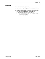
Startup 

1. Ensure that the system is safe to start.

2. Using the front door panel on the isolator, turn on the system components

in the following sequence:

S

Booth Control Panel

S

After Filter Control Panel

S

Spectrum HD Generation II Feed Center

3. Ensure the emergency stop buttons are pulled out on the booth, feed

center, and after filter panels.

4. Make sure compressed air is being supplied to the feed center at 6.5 bar

(95 psi) and that air pressures are adjusted properly.

Summary of Contents for Spectrum HD Generation II

Page 1: ...192568_03 Issued 05 20 This document is available on the Internet at http emanuals nordson com finishing Find your nearest centre at www nordson com directory For parts and technical support call your...

Page 2: ...o Nordson GmbH Heinrich Hertz Strasse 42 40699 Erkrath Germany Notice This is a Nordson Corporation publication which is protected by copyright Original copyright date 2014 No part of this document ma...

Page 3: ...Revision Date Change 02 19 05 2017 Wiring diagrams updated 02 258 424 02 19 05 2017 Parts list to include complete pinch valve assembly 03 25 03 2020 Images 03 27 03 2020 Parts list also inc XXL 03 29...

Page 4: ...perated on its own or in conjunction with other equipment In order to be in full compliance with the CE machinery directive and its amendments the customer is obliged to respect the applicable regulat...

Page 5: ...s 2 7 Electric Requirements 2 7 Air Requirements 2 7 Installation 3 1 Unpacking 3 1 Preparing for Installation 3 1 Damper Installation 3 1 Extraction Duct Connection 3 1 Electrical Connections 3 2 Pne...

Page 6: ...Dump Valve Sleeve 5 4 Level Sensors 5 5 Sieve Screen 5 5 Troubleshooting 6 1 Troubleshooting Chart 6 1 Parts 7 1 Introduction 7 1 Using the Illustrated Parts List 7 1 HD Hopper and Sieve 7 3 XXL HD Ho...

Page 7: ...and regulations and are physically capable of performing their assigned tasks Intended Use Use of Nordson equipment in ways other than those described in the documentation supplied with the equipment...

Page 8: ...ss obvious dangers in the workplace that often cannot be completely eliminated such as hot surfaces sharp edges energized electrical circuits and moving parts that cannot be enclosed or otherwise guar...

Page 9: ...t more than 1 megohm as measured with an instrument that applies at least 500 volts to the circuit being evaluated Personnel working inside the FeedCenter must be grounded S There is a possible igniti...

Page 10: ...Safety 1 4 Part 7192568 03 E 2020 Nordson Corporation...

Page 11: ...ng and powder feed system using the Nordson HDLV technology along with ultrasonic sieve level sensors virgin feed and electrical pneumatic controls via a touch screen operator interface The SHD II pro...

Page 12: ...ough the powder feed pumps hoses and guns to clean them of powder This also cleans the sieve section and hopper itself leaving minimal cleaning from the operator The reclaim and virgin powder transfer...

Page 13: ...el interface 2 HD hopper 3 Virgin powder feed lance 4 HDLV transfer pump 5 VBF virgin powder feed holder 6 Pneumatic gauge for feed hopper 7 Pneumatic regulator for feed hopper 8 HDLV pump panel 9 Add...

Page 14: ...Corporation HD Hopper System 1 2 1 2 3 4 5 7 8 6 9 Figure 2 3 Spectrum HD Generation II Hopper Assembly 1 Sieve inlet 2 Plug sieve inlet 3 Sieve screen 4 Ultrasonic probe 5 Handle locking 6 Level sens...

Page 15: ...reset 6 Emergency stop 7 Main power On Off Not Shown Valve island Regulator recovery powder pump mounted locally to twin cyclone Note The Spectrum HD Generation II Feed Centre in its standard form is...

Page 16: ...lbs depending on configuration and options 2253 1963 1654 1601 1495 Figure 2 5 Spectrum HD Gen II Feed Center Dimensions Note System shown is without controls as there are 2 versions of control panel...

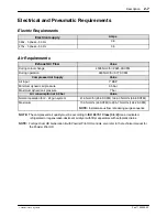
Page 17: ...ure 6 5 bar Maximum dynamic air pressure 7 bar Air consumption at 6 9 bar Value Normal operation for 2 24 gun system 41 6 Nm3 hr 25 9 SCFM to 94 3 Nm3 hr 58 8 SCFM Maximum 73 9 Nm3 hr 46 SCFM to 295 7...

Page 18: ...Description 2 8 Part 7192568 03 E 2020 Nordson Corporation...

Page 19: ...aring for Installation WARNING Allow only authorized Nordson personnel to complete Position the SHD II feed center on a level floor according to the general layout drawing supplied by Nordson applicat...

Page 20: ...protection from the power supply Refer to the foldout wiring diagrams and schematics at the end of this manual for more information Before starting up the SHD II feed center turn on the feed center po...

Page 21: ...egulator During a color change cycle when the operator selects Pump Purge the valve opens and allows air at line pressure to flow through the pump and the 16 mm suction and delivery powder tubing to c...

Page 22: ...poration Checks to Complete Installation Default Parameters Figure 3 1 Floor Fixing Locations 1 Ensure the unit is level and fixed to the floor at locations highlighted in red below Figure 3 2 Groundi...

Page 23: ...age S Pressurise the unit with the desired teach pressure TP1 S Press the Edit button 2 s until the LED flashes S Let go of the Edit button The current teach pressure TP1 is saved as the switching pre...

Page 24: ...sion meter ensure the tension of the screen mesh is 20 25 N cm If it is outside of this reading replace it A loose or worn screen can tear and cause contamination Figure 3 5 Sieve Probe Tightening Usi...

Page 25: ...the suction by 1 hole towards number 6 For each hole the damper will still Open fully 100 The different hole position determines the restriction for the Closed production position Hole 1 means the dam...

Page 26: ...lue 1 Active job number 2 2 Amplitude 50 3 Sweep bandwidth 200 Hz 4 Sweep frequency 50 5 Frequency limit minimum 30000 6 Frequency limit maximum 38000 7 Power unit W 30 8 Power window minimum W 0 9 Po...

Page 27: ...o perform the following tasks Follow the safety instructions in this document and all other related documentation The SHD Spectrum HD Gen II feed center has 2 options of controls S Feed Center Stand A...

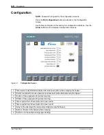
Page 28: ...the operator to the configuration screen Only trained operators or maintenance staff should use this screen A password is required for ac cess to this screen 9 HDLV Reclaim Powder Enables the reclaim...

Page 29: ...parate selector buttons on the Touch Screen The transfer pumps are disabled when the sieve is turned off Reclaim Transfer Pump Operation The reclaim pump operates continuously as long as it is turned...

Page 30: ...than 3 minutes field adjustable the low powder alarm is turned on Silencing the Low Powder Alarm Touch the alarm silence icon on the touch screen Startup 1 Ensure that the system is safe to start 2 Us...

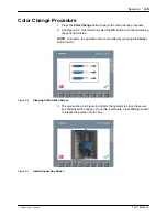
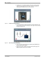
Page 31: ...OK button to continue cleaning the guns from inside NOTE At anytime the operation can be cancelled by pressing the Cancel button red X Figure 4 2 Cleaning Confirmation Screen 3 The screen shown in Fi...

Page 32: ...Load Countdown Screen 5 The screen in Figure 4 6 directs the operator to connect the hoses to the extract position and bring the exhaust pipe of the hopper into the cleaning position by turning it 180...

Page 33: ...nual cleaning is complete use the Virgin HDLV Pump Cleaning button and the Reclaim HDLV Pump Cleaning button to clean the virgin and reclaim pumps 10 When all cleaning is complete and system is clear...

Page 34: ...n Screen 1 Time assist air will start after powder clears low lever probe when emptying the hopper 2 Start of countdown time once powder clears low level probe when emptying the hopper 3 On time of th...

Page 35: ...e color change process but do not install a new powder source 3 If you will be shutting down the powder feed center for maintenance repair or an extended period of time perform these steps a Press the...

Page 36: ...sfer pump is functioning OP 8 Prodigy High Capacity HDLV Transfer Pump supply air 4 8 bar No restriction or blockage in the powder delivery hose Visual inspection Pneumatic Supply Check incoming air p...

Page 37: ...of the hopper lid TT 2000 No powder leakage is allowed In case of powder leakage adjust the lid hinges and check the con dition of the hopper seals Visual inspection Sieve Check the tension of the si...

Page 38: ...ransfer Pump Maintenance For more detailed maintenance and repair information refer to the Prodigy HDLV High Capacity Pump manual 1092270 08 Cleaning CAUTION Clean any impacted powder with clean cloth...

Page 39: ...the special tool to remove the upper pinch valve nut to allow the assembly to drop 4 Place the valve body on a solid surface 5 Remove the lower pinch valve nut and outlet adaptor 6 Remove the damaged...

Page 40: ...to the new sensor 5 Place hand in front of the sensor to ensure the controller screen reads the sensor Sieve Screen WARNING Allow only qualified personnel to perform the following tasks Follow the saf...

Page 41: ...ton pressed Reset the E Stop Final filters clogged Check the final filters The fan is shut off automatically if the pressure across the filters reaches 3 in w c If the filters are clogged check the ca...

Page 42: ...filter gaskets and media for damage Replace filters as necessary Cross drafts interfering with exhaust fan draw Check for cross drafts at the enclosure opening Eliminate or divert drafts Fan rotation...

Page 43: ...be no more than three parts reclaim to one part virgin powder Uneven distribution of powder in feed source Check the powder and the fluidizing plate for contamination as previously described 6 Large d...

Page 44: ...uit is defective Check the wiring Repair or replace as needed No air supply to solenoid valve assembly or solenoid valve not opening Check the air supply to the solenoid valve assembly on the side of...

Page 45: ...ective No signal from screen to controller Turning the switch to Pump Purge position should turn on signal Check wiring repair or replace as needed Purge solenoid valves or wiring defective Check wiri...

Page 46: ...ve Color Change start signal from feed center The feed center passes signals for color change to the gun positioner 1 electrical panel which then communicates with the Control system Check the wiring...

Page 47: ...cated in the main system panel is activated by signal from the gun positioner control panel Solenoid valve sends air signal to large pilot valve that provides air to the blowoff nozzles Make sure main...

Page 48: ...he illustration The number in the Part column is the Nordson Corporation part number A series of dashes in this column means the part cannot be ordered separately The Description column gives the part...

Page 49: ...Parts 7 2 Part 7192568 03 E 2020 Nordson Corporation 1 2 or 24 3 4 5 18 19 17 11 12 20 21 7 6 8 9 13 14 15 16 10 22 23 25 Figure 7 1 SHD Spare Parts...

Page 50: ...CONE 2 063X2 250X 094 1 22 1018596 ISOLATOR VIBRATION 32MM DIA X 8MM STUDS 4 D 23 1076854 KIT SERVICE 220V VIB MOTOR W CAP 1 24 R768675 SCREEN A300 SIEVE 300 MICRON US REPAIR 1 A B 24 R768676 SCREEN A...

Page 51: ...Parts 7 4 Part 7192568 03 E 2020 Nordson Corporation 1 2 or 23 3 4 5 17 18 16 10 11 19 20 7 6 8 9 12 13 14 15 17 21 22 25 Figure 7 2 SHD XXL Spare Parts...

Page 52: ...1018596 ISOLATOR VIBRATION 32MM DIA X 8MM STUDS 4 D 22 1076854 KIT SERVICE 220V VIB MOTOR W CAP 1 23 7035217 SCREEN A425 SIEVE 300 MICRON US REPAIR 1 A B 23 7035216 SCREEN A425 SIEVE 250 MICRON US REP...

Page 53: ...T GROUNDING ANTISTATIC HOSE 12 7MM NOTE For additional tubing information and parts lists refer to technical manual Powder Tubing Antistatic 1070652A Air Tubing Powder Tubing Fittings and Miscellaneou...

Page 54: ...Nordson Corporation Section 8 System Diagrams NOTE Electrical and Pneumatic drawings will be supplied with the system For more information please contact your Nordson representative Diagram Sheets Spe...

Reviews: