background image

31

SYMPTOM: The displays of the console do not 

function properly

a.  

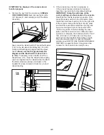
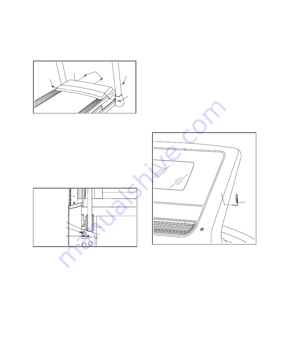
Remove the key from the console and UNPLUG 

THE POWER CORD. Next, remove the five #8 x 

3/4" Screws (2), and carefully pivot off the Motor 

Hood (65).


   Next, locate the Reed Switch (116) and the Magnet 

(114) on the left side of the Pulley (49). Turn the 

Pulley until the Magnet is aligned with the Reed 

Switch. Make sure that the gap between the 

Magnet and the Reed Switch is about 1/8 in. 

(3 mm). If necessary, loosen the #8 x 3/4" Pan 

Head Screw (111), move the Reed Switch slightly, 

and then retighten the Pan Head Screw. Reattach 

the Motor Hood (see above)and walk on the 

treadmill for a few minutes to check for a correct 

speed reading. 

b.   If the console does not boot up properly, or 

if the console freezes and does not respond, 

reset the console to the factory default settings. 

IMPORTANT: Doing this will erase all the 

custom settings you have made to the console. 

Resetting the console requires two people. First, 

press the power switch into the off position. Next, 

locate the small reset opening (A) on the right side 

of the console. Using a bent paper clip (B), press 

and hold the reset button inside the opening, and 

have a second person press the power switch 

into the on position. Continue holding the reset 

button until the console turns on. When the reset 

operation is complete, the console will turn off and 

then turn back on. If it does not, use the power 

switch to turn the treadmill off and then on again. 

Once the console turns on, check for firmware 

updates (see HOW TO USE THE MAINTENANCE 

SECTION on page 26). Note: It may take a few 

minutes for the console to be ready for use.

65

2

2

2

2

a

114

111

116

1/8 in.

49

Top 

View

A

b

B

Summary of Contents for NETL10819.0

Page 1: ...rence Serial Number Decal USER S MANUAL iconeurope com CUSTOMER SERVICE UNITED KINGDOM Call 0330 123 1045 From Ireland 053 92 36102 Website iconsupport eu E mail csuk iconeurope com Write ICON Health...

Page 2: ...als If a decal is missing or illegible call the telephone number on the front cover of this manual and request a free replacement decal Apply the decal in the location shown Note The decals may not be...

Page 3: ...o not wear loose clothes that could become caught in the treadmill Athletic support clothes are recom mended for both men and women Always wear athletic shoes Never use the treadmill with bare feet we...

Page 4: ...the treadmill 25 When folding or moving the treadmill make sure that the storage latch is holding the frame securely in the storage position Do not operate the treadmill while it is folded 26 Do not...

Page 5: ...of this manual To help us assist you note the product model number and serial number before contacting us The model number and the location of the serial number decal are shown on the front cover of t...

Page 6: ...umber is the quantity used for assembly Note If a part is not in the hardware kit check to see whether it is preattached Extra parts may be included 5 16 x 3 4 Screw 8 2 8 x 3 4 Screw 2 6 8 x 1 Screw...

Page 7: ...eu If you do not have internet access call Customer Service see the front cover of this manual To register your product and activate your warranty in Australia email or post the following information...

Page 8: ...ith a 8 x 1 2 Ground Screw 10 94 90 10 77 C B D 3 4 63 62 101 94 13 13 90 7 13 81 4 Hold the Right Upright 90 against the Base 94 Make sure not to pinch the Upright Wire 81 Attach the Right Upright 90...

Page 9: ...the tab E on one of the Cover Brackets 18 into the slot F in the Left Upright 89 and attach the Cover Bracket with two 8 x 1 2 Screws 1 See the right drawing Attach the other Cover Bracket 18 to the R...

Page 10: ...onsole base assembly in place during assembly 8 81 H 90 8 Identify the right handrail assembly I Remove and discard the two indicated screws J Next carefully raise the Pulse Crossbar 93 enough to allo...

Page 11: ...th the help of a second person hold the console assembly L near the console base assembly G Connect the wires M from the console base assembly G to the wires N from the console assembly L The connecto...

Page 12: ...ssembly Attach the console assembly L with two 5 16 x 1 3 4 Screws 12 and two 5 16 Star Washers 11 start both Screws and then tighten them Note Only one side is shown 11 O 81 G L 11 12 12 Attach the S...

Page 13: ...8 on each side of the handrail assembly Next identify the Right Handrail Cover 26 Insert the tab Q on the Right Handrail Cover into the right handrail assembly I in the loca tion shown Then press the...

Page 14: ...x 3 4 Patch Screws 4 that you removed in step 5 and four 5 16 Star Washers 11 start all four Patch Screws and then tighten them 11 4 11 90 89 105 4 16 Insert the Tray 31 from the front of the treadmi...

Page 15: ...ker S is facing the treadmill Attach the Latch Crossbar to the brackets T on the Frame 56 with the two 5 16 x 3 4 Patch Screws 4 that you just removed and two 5 16 Star Washers 11 56 41 S T T 4 4 11 1...

Page 16: ...lastic on the treadmill decals remove the plastic To protect the floor or carpet place a mat under the treadmill To avoid damage to the console keep the treadmill out of direct sunlight Keep the inclu...

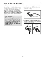
Page 17: ...o the socket on the treadmill 2 Plug the power cord into an appropriate outlet that is properly installed and earthed in accordance with all local codes and ordinances GR RU HU Socket on Treadmill Pow...

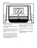
Page 18: ...ll with the touch of a button As you exercise the console will display instant exercise feedback You can even measure your heart rate using the handgrip heart rate monitor See page 28 for information...

Page 19: ...ed see HOW TO USE THE EQUIPMENT SETTINGS SECTION on pages 25 For simplicity all instructions in this section refer to kilometers HOW TO USE THE TOUCH SCREEN The console features a tablet with a full c...

Page 20: ...k See HOW TO USE THE MAINTENANCE SECTION on page 26 for more information 6 Calibrate the incline system First touch your name in the upper left corner Next select the settings main menu Then select th...

Page 21: ...kly If you press one of the numbered speed buttons the walking belt will gradually change speed until it reaches the selected speed setting To stop the walking belt press the Stop button or tap the mi...

Page 22: ...addition make sure that your hands are clean To measure your heart rate stand on the foot rails and hold the contacts with your palms for approximately ten seconds avoid moving your hands When your pu...

Page 23: ...me way as the manual mode see pages 21 to 22 When you reach the end of the workout the walking belt will slow to a stop and a workout summary will appear on the screen After you view the workout summa...

Page 24: ...STANCE OR TIME WORKOUT Note To use a distance or time workout the console must be connected to a wireless network see HOW TO USE THE WIRELESS NETWORK MODE on page 26 An iFit account is also required 1...

Page 25: ...he fan if desired See step 7 on page 22 10 When you are finished exercising remove the key from the console See step 8 on page 22 For more information about iFit go to iFit com HOW TO USE THE WORKOUT...

Page 26: ...lways designed to improve your exer cise experience 4 Calibrate the incline system of the treadmill Touch the Calibrate Incline button Then touch the Begin button to calibrate the incline system The t...

Page 27: ...s after following these instructions go to support iFit com for assistance 5 Exit the wireless network mode To exit the wireless network mode touch the back button on the screen HOW TO USE THE SOUND S...

Page 28: ...SHIONS The treadmill features a cushioning system that reduces the impact as you walk or run on the treadmill To adjust the cushions first remove the key from the console and unplug the power cord You...

Page 29: ...direct sunlight Do not leave the treadmill in the storage position in tem peratures above 85 F 30 C HOW TO MOVE THE TREADMILL Before moving the treadmill fold it as described at the left CAUTION Make...

Page 30: ...After the power cord has been plugged in make sure that the key is inserted into the console c Check the power switch located on the treadmill frame near the power cord If the switch protrudes as show...

Page 31: ...nsole freezes and does not respond reset the console to the factory default settings IMPORTANT Doing this will erase all the custom settings you have made to the console Resetting the console requires...

Page 32: ...g belt needs more lubricant see the front cover of this manual d If the walking belt still slows when walked on see the front cover of this manual SYMPTOM The walking belt is not centered between the...

Page 33: ...ic Exercise If your goal is to strengthen your cardiovascular system you must perform aerobic exercise which is activity that requires large amounts of oxygen for prolonged periods of time For aerobic...

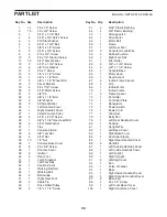
Page 34: ...ion Decal 44 1 Walking Platform 45 1 Walking Belt 46 2 Belt Guide 47 1 Right Rear Foot 48 4 Cable Tie 49 1 Drive Roller Pulley 50 2 1 4 x 1 1 4 Screw 51 2 9 32 Plastic Bushing 52 4 3 8 Plastic Bushing...

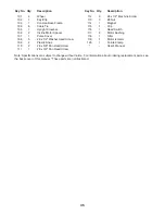
Page 35: ...09 2 Plastic Snap 110 2 8 x 5 8 Pan Head Screw 111 1 8 x 3 4 Pan Head Screw 112 3 8 x 1 2 Machine Screw 113 3 8 Nut 114 1 Magnet 115 1 Clip 116 1 Reed Switch 117 2 Motor Bushing 118 1 Filter 119 1 Mot...

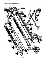
Page 36: ...37 34 30 59 34 30 59 37 37 1 39 1 39 2 57 2 40 40 47 2 2 37 37 37 37 37 35 35 35 35 35 35 35 35 15 2 54 55 39 1 35 35 35 39 1 35 1 39 35 4 34 3 41 53 34 6 4 11 11 108 108 51 50 51 117 111 20 73 118 1...

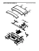
Page 37: ...37 66 75 65 72 78 2 2 2 2 2 2 2 67 67 33 29 69 70 16 71 33 33 52 52 23 23 33 71 106 2 68 68 68 2 68 2 68 76 74 EXPLODED DRAWING B Model No NETL10819 0 R0519A...

Page 38: ...90 101 101 101 101 91 100 99 13 7 13 63 7 13 13 7 13 2 97 2 86 79 25 107 2 2 11 28 86 28 11 81 93 9 2 2 2 2 2 2 5 9 5 88 87 2 1 1 2 2 110 2 2 95 85 11 4 105 4 11 1 11 4 1 1 1 10 58 96 18 18 2 2 26 2...

Page 39: ...39 31 64 80 103 32 36 38 2 2 2 2 2 14 2 2 2 2 2 2 2 2 14 27 2 2 92 2 98 98 2 2 2 2 2 8 2 2 2 2 2 11 8 11 12 12 2 104 104 104 2 2 EXPLODED DRAWING D Model No NETL10819 0 R0519A...

Page 40: ...T and the EXPLODED DRAWING near the end of this manual ORDERING REPLACEMENT PARTS This electronic product must not be disposed of in municipal waste To preserve the environment this product must be re...

Reviews: