background image

9

7

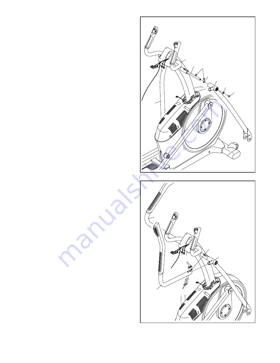
7.  Using a plastic bag to keep your fingers clean, 

apply some of the included grease to the Pivot 

Axle (35) and to two 16mm Wave Washers (54).

  Insert the Pivot Axle (35) through the Upright (4) 

and center it. 

Tip: It may be helpful to use a 

rubber mallet.

  Identify the Right Upper Body Leg (60) and  

orient it as shown.

  Slide a 16mm Wave Washer (54) and the Right 

Upper Body Leg (60) onto the right side of the 

Pivot Axle (35).

  Repeat these actions for the Left Upper Body 

Leg (46).

  Tighten an M8 x 13mm Screw (82) and an M8 

Washer (97) into each end of the Pivot Axle (35) 

at the same time.

60

54

46

82

97

35

4

Grease

8

8.  Identify the Right Upper Body Arm (61) and ori-

ent it as shown.

  Slide the Right Upper Body Arm (61) onto the 

Right Upper Body Leg (60). 

  Attach the Right Upper Body Arm (61) with two 

M8 x 38mm Bolts (96) and two M8 Locknuts 

(102).

 Make sure that the Locknuts are in the 

hexagonal holes. 

  Repeat this step for the Left Upper Body  

Arm (47).

Hexagonal 

Holes

60

61

47

96

102

Summary of Contents for E 12.2 Elliptical

Page 1: ...ove for reference www iconeurope com Serial Number Decal CUSTOMER SERVICE UNITED KINGDOM Call 08457 089 009 From Ireland 053 92 36102 Website www iconsupport eu E mail csuk iconeurope com Write ICON H...

Page 2: ...shown Note The decal s may not be shown at actual size NORDICTRACK is a registered trademark of ICON IP Inc WARNING DECAL PLACEMENT 2 IMPORTANT PRECAUTIONS 3 BEFORE YOU BEGIN 4 PART IDENTIFICATION CH...

Page 3: ...each side To protect the floor or carpet from dam age place a mat under the elliptical 7 Inspect and properly tighten all parts regu larly Replace any worn parts immediately 8 Keep children under age...

Page 4: ...s manual To help us assist you note the product model number and serial number before contacting us The model number and the location of the serial number decal are shown on the front cover of this ma...

Page 5: ...al The number following the key number is the quantity needed for assembly Note If a part is not in the hardware kit check to see if it has been preassembled Extra parts may be included M8 x 13mm Scre...

Page 6: ...6 104 105 2 With the help of a second person place some of the packing materials not shown under the front of the Frame 1 Have the second per son hold the Frame to prevent it from tipping while you c...

Page 7: ...to prevent it from tipping while you complete this step Attach the Rear Stabilizer 2 to the Frame 1 with two M10 x 122mm Screws 104 and two M10 Split Washers 105 Remove the packing materials from unde...

Page 8: ...d avoid damaging the tabs Tabs 4 1 105 105 99 99 6 6 See the inset drawing Locate the wire tie in the lower end of the Upright 4 Tie the wire tie to the Upper Wire 110 and to the Fan Extension Wire 14...

Page 9: ...the right side of the Pivot Axle 35 Repeat these actions for the Left Upper Body Leg 46 Tighten an M8 x 13mm Screw 82 and an M8 Washer 97 into each end of the Pivot Axle 35 at the same time 60 54 46 8...

Page 10: ...Upright 4 connect the wires on the Console to the Upper Wire 110 to the Fan Extension Wire 146 and to the Sensor Wires 63 144 Insert the excess wire into the Upright 4 or into the Console 7 63 110 144...

Page 11: ...lide an M8 Washer 97 and an Axle Spacer 77 onto an M8 x 13mm Screw 82 and tighten the Screw a few turns into the Pedal Arm Axle 64 While a second person holds the front end of the Right Pedal Arm 58 i...

Page 12: ...ct the Fan Extension Wire 146 to the Fan Wire 136 Tip Avoid pinching the wires Press the Shield Cover 75 onto the Left and Right Shields 73 74 75 4 73 74 Avoid pinching the wires 146 136 14 14 Orient...

Page 13: ...ont Console Cover 79 around the Upright 4 by pressing it into the Rear Console Cover 80 79 4 80 101 16 16 Orient the Rear Upright Cover 81 as shown Attach the Rear Upright Cover 81 to the Upright 4 wi...

Page 14: ...66 60 83 94 101 69 18 Identify the Right Upper Body Leg Inner Cover 83 and orient it as shown Attach the Right Upper Body Leg Inner Cover 83 to the Right Upper Body Leg 60 with an M4 x 16mm Screw 101...

Page 15: ...tures above 122 F 50 C or below 14 F 10 C Do not excessively bend or stretch the sensor when using or storing the heart rate monitor To clean the sensor use a damp cloth and a small amount of mild soa...

Page 16: ...the indicated end of the power cord into the socket on the frame 2 Plug the power cord into an appropriate outlet that is properly installed and earthed in accordance with all local codes and ordinan...

Page 17: ...will roll on the wheels Carefully move the elliptical to the desired location and then lower it to the floor HOW TO ADJUST THE POSITIONS OF THE PEDALS Each pedal can be adjusted to several positions...

Page 18: ...however for variety you can turn the pedals in the opposite direction To dismount the elliptical wait until the pedals come to a complete stop Note The elliptical does not have a free wheel the pedals...

Page 19: ...ole also features revolutionary iFit technol ogy that enables the console to communicate with your wireless network through an optional iFit module With iFit you can download personalized workouts cre...

Page 20: ...Begin pedaling or press any button on the console to turn on the console See HOW TO TURN ON THE POWER at the left 2 Select the manual mode Press the Manual button on the console to select the manual...

Page 21: ...ted this display mode will show the elapsed time When a workout is selected this display mode will show the time remaining in the workout The matrix offers several display tabs Press the Display butto...

Page 22: ...beats one or two dashes will appear and then your heart rate will be shown For the most accurate heart rate reading hold the contacts for at least 15 seconds If the display does not show your heart r...

Page 23: ...rent resis tance level ramp incline level and or target rpm is programmed for the next segment the resistance level ramp incline level and or target rpm will appear in the display for a few seconds to...

Page 24: ...rovide motivation Your actual pedaling speed may be slower than the target rpm Make sure to pedal at a speed that is comfortable for you Note The calorie goal is an estimate of the number of calories...

Page 25: ...s the iFit button Note You may be able to access demo workouts through these options even if you do not insert an iFit module To compete in a race that you have previously scheduled press the Compete...

Page 26: ...s you to view usage information select a unit of measurement and adjust the contrast level of the display When an iFit module is connected to the console you can also use the information mode to choos...

Page 27: ...pear when you turn on the console Press the Enter button repeatedly to select the manual mode main menu or the iFit menu as the default menu 8 Check the status of the iFit module if desired Press the...

Page 28: ...e handgrip heart rate monitor or if the dis played heart rate appears to be too high or too low see step 5 on page 22 If the console does not display your heart rate when you use the chest heart rate...

Page 29: ...c Exercise If your goal is to strengthen your cardiovascular system you must perform aerobic exercise which is activity that requires large amounts of oxygen for prolonged periods of time For aerobic...

Page 30: ...lles Stretch With one leg in front of the other reach forward and place your hands against a wall Keep your back leg straight and your back foot flat on the floor Bend your front leg lean forward and...

Page 31: ...Wave Washer 55 2 Small Axle Cover 56 4 Roller Arm Bushing 57 8 Arm Bearing 58 1 Right Pedal Arm 59 1 Right Roller Arm 60 1 Right Upper Body Leg 61 1 Right Upper Body Arm 62 1 Left Grip 63 1 Right Sens...

Page 32: ...ft Pedal Plate 129 1 Left Pedal Handle 130 2 Pedal Pin 131 2 Pedal Spring 132 2 M10 x 140mm Bolt 133 2 M6 Acorn Nut 134 1 Fan Grill 135 1 Fan Bracket 136 1 Fan Wire 137 2 Saddle Bracket 138 1 Right Pe...

Page 33: ...1 78 78 86 86 88 85 85 89 90 50 91 102 108 108 113 141 142 120 121 121 122 102 115 32 126 127 108 127 126 17 123 112 28 41 41 105 104 6 34 34 124 125 125 124 105 50 104 101 101 109 109 30 30 25 3 10 1...

Page 34: ...57 57 60 101 61 66 68 101 62 52 64 64 65 67 70 72 69 83 87 76 77 77 77 101 101 77 95 95 95 95 95 95 82 147 82 147 82 82 82 82 96 96 98 98 94 94 97 97 97 97 97 97 97 97 97 97 100 100 100 100 101 101 1...

Page 35: ...7 36 36 99 99 35 37 81 54 54 144 63 79 73 75 80 101 105 105 96 96 9 102 96 5 5 5 107 5 5 5 5 5 101 101 101 101 101 102 110 119 118 116 116 117 111 146 134 135 136 93 93 137 137 139 139 140 140 74 Mode...

Page 36: ...the EXPLODED DRAWING near the end of this manual ORDERING REPLACEMENT PARTS This electronic product must not be disposed of in municipal waste To preserve the environment this product must be recycled...

Reviews: