background image

3

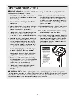
1. Read all instructions in this manual and all

warnings on the exercise cycle before using
the exercise cycle. 

2. Use the exercise cycle only as described in

this manual.

3. It is the responsibility of the owner to ensure

that all users of the exercise cycle are ade-
quately informed of all precautions. 

4. The exercise cycle is intended for home use

only. Do not use the exercise cycle in 
a commercial, rental, or institutional setting.

5. Keep the exercise cycle indoors, away from

moisture and dust. Place the exercise cycle
on a level surface, with a mat beneath it to
protect the floor or carpet. Make sure that
there is enough clearance around the exer-
cise cycle to mount, dismount, and use it.

6. Inspect and properly tighten all parts regular-

ly. Replace any worn parts immediately.  

7. Keep children under the age of 12 and pets

away from the exercise cycle at all times.

8. Wear appropriate clothes while exercising;

do not wear loose clothes that could become
caught on the exercise cycle. Always wear
athletic shoes for foot protection.

9. The exercise cycle should not be used by

persons weighing more than 300 lbs. 
(136 kg).

10. The pulse sensor is not a medical device.

Various factors, including the user's move-
ment, may affect the accuracy of heart rate
readings. The pulse sensor is intended only
as an exercise aid in determining heart rate
trends in general.

11. Always keep your back straight while using

the exercise cycle; do not arch your back.

12. If you feel pain or dizziness while exercising,

stop immediately and cool down.

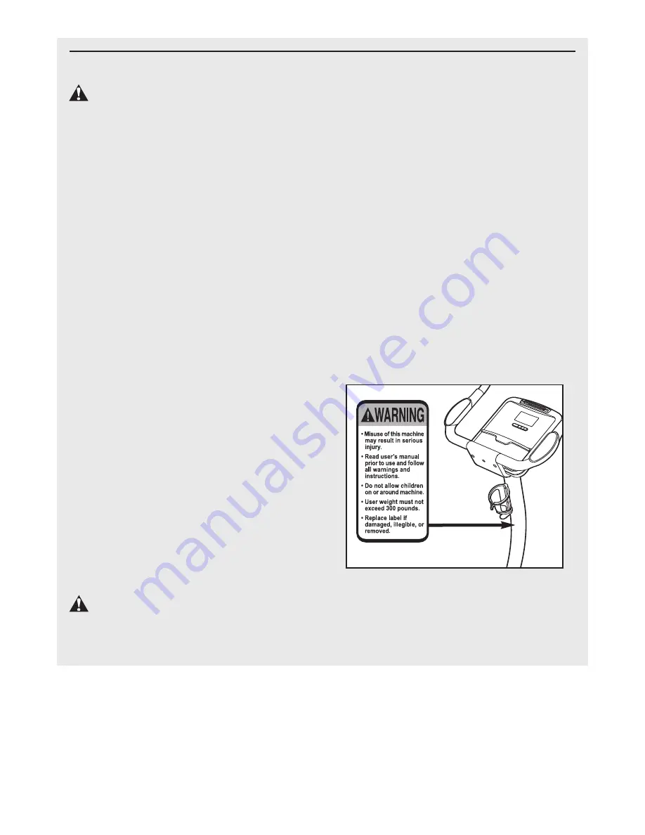
13. The decal shown below has been placed on

the exercise cycle. If the decal is missing or
illegible, call the toll-free telephone number
on the front cover of this manual and order a
free replacement decal. Apply the decal in
the location shown.

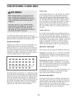
WARNING:

Before beginning this or any exercise program, consult your physician.

This is especially important for persons over the age of 35 or persons with pre-existing health prob-
lems. Read all instructions before using. ICON assumes no responsibility for personal injury or
property damage sustained by or through the use of this product.

IMPORTANT PRECAUTIONS

WARNING:

To reduce the risk of serious injury, read the following important precau-

tions before using the exercise cycle.

Summary of Contents for Audiorider U300 Bike

Page 1: ...damaged or missing PLEASE CONTACT OUR CUSTOMER SERVICE DEPARTMENT DIRECTLY CALL TOLL FREE 1 888 825 2588 Mon Fri 6 a m 6 p m MST Sat 8 a m 4 p m MST ON THE WEB www nordictrackservice com Model No NTEX3196 0 Serial No Visit our website at www proform com new products prizes fitness tips and much more Visit our website at www healthrider com new products prizes fitness tips and much more Visit our w...

Page 2: ...4 ASSEMBLY 5 HOW TO OPERATE THE EXERCISE CYCLE 10 MAINTENANCE AND TROUBLESHOOTING 17 CONDITIONING GUIDELINES 18 PART LIST 22 EXPLODED DRAWING 23 ORDERING REPLACEMENT PARTS Back Cover LIMITED WARRANTY Back Cover NordicTrack is a registered trademark of ICON IP Inc ...

Page 3: ...otection 9 The exercise cycle should not be used by persons weighing more than 300 lbs 136 kg 10 The pulse sensor is not a medical device Various factors including the user s move ment may affect the accuracy of heart rate readings The pulse sensor is intended only as an exercise aid in determining heart rate trends in general 11 Always keep your back straight while using the exercise cycle do not...

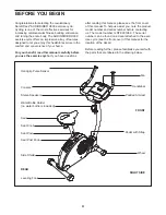
Page 4: ...ions after reading this manual please see the front cover of this manual To help us assist you note the product model number and serial number before contacting us The model number is NTEX3196 0 The serial number can be found on a decal attached to the exer cise cycle see the front cover of this manual for the location of the decal Before reading further please familiarize yourself with the parts ...

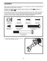
Page 5: ...w each drawing is the key number of the part from the PART LIST on page 22 The number following the parentheses is the quantity used in assembly Note Some small parts may have been preassembled for shipping If a part is not in the parts bag check to see if it has been preassembled M10 x 85mm Button Screw 56 4 M10 x 50mm Button Screw 48 3 M6 x 10mm Screw 60 2 M6 x 30mm Button Screw 46 4 M4 x 19mm S...

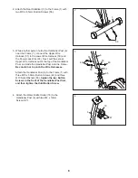
Page 6: ...ut of the top of the Handlebar Post and slide the Handlebar Post onto the Frame Be careful not to pinch the Wire Harnesses Attach the Handlebar Post 6 to the Frame 1 with three M10 x 50mm Button Screws 48 and three M10 Split Washers 55 tighten the two Button Screws in the front of the Handlebar Post first and then tighten the third Button Screw 1 56 3 3 55 55 55 48 48 1 51 65 50 6 2 4 6 18 47 4 At...

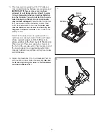
Page 7: ... may become damaged Press the tabs on the bat tery covers and remove the battery covers Next insert four batteries into the Console make sure that the batteries are oriented as shown by the diagrams inside the Console Then reattach the battery covers Note The Console 9 can be operated with an optional power supply instead of batteries To pur chase a power supply call the toll free tele phone numbe...

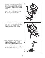
Page 8: ... the bottom of the Console 9 Attach the Bottom Handlebar Cover to the Handlebar 7 and the Top Handlebar Cover 30 with two M4 x 16mm Screws 54 and one M4 x 12mm Screw 64 7 While another person holds the Console 9 near the Handlebar 7 connect the wire harness on the Console to the Upper Wire Harness 51 Next con nect the pulse wire on the Console to the Pulse Grip Wire 10 Note The remaining wire on t...

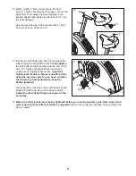
Page 9: ...nto the Left Crank Arm 15 Tighten the Right Pedal not shown clockwise into the Right Crank Arm Important Tighten both Pedals as firmly as possible After using the exercise cycle for one week retighten the Pedals For best performance keep the Pedals tightened Press the tab on the side of the Left Pedal 40 and adjust a Pedal Strap 25 to the desired position Adjust the other Pedal Strap not shown in ...

Page 10: ...sure that the knob is engaged in one of the adjustment holes in the seat post Then turn the knob clockwise to tighten it HOW TO ADJUST THE LATERAL POSITION OF THE SEAT To adjust the lateral position of the seat first loosen the seat knob a few turns Then move the seat forward or backward to the desired posi tion and firmly tight en the seat knob HOW TO ADJUST THE PEDAL STRAPS To adjust the pedal s...

Page 11: ...t System The iFIT Interactive Workout System enables the console to accept iFIT Cards containing workout programs designed to help you achieve specif ic fitness goals For example lose unwanted pounds with the 8 week Weight Loss program iFIT programs control the resistance of the pedals while the voice of a personal trainer coaches you and motivates you through your workouts One iFIT Card with thre...

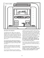
Page 12: ... you have pedaled in miles or kilo meters The center of the display will show the resistance setting of the pedals for a few seconds each time the resistance setting changes To view the approximate number of calories that you are burning per hour and the approximate number of calories that you have burned during your workout press the Display button You can also view selected information at a larg...

Page 13: ...ver use alcohol abrasives or chemicals to clean the contacts Turn on the fan if desired To turn on the fan at high speed press the Fan button To turn on the fan at low speed press the Fan button a second time To select the auto mode press the Fan button again when the auto mode is selected the speed of the fan will auto matically increase or decrease as you increase or decrease your pedaling speed...

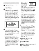
Page 14: ... resistance of the pedals will then change As you exercise you will be prompted to keep your pedaling pace near the target pace setting for the current segment When an upward pointing arrow appears in the display increase your pace When a downward pointing arrow appears decrease your pace When no arrow appears maintain your current pace Important The target pace settings are intended only to provi...

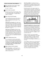
Page 15: ...p exercising or select a different program before the program ends Heart rate program 2 is divided into 30 one minute segments One target heart rate setting is programmed for each segment Note The same target heart rate setting may be programmed for consecutive segments During the program the program profile in the display will show your progress The flashing col umn of the profile represents the ...

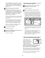
Page 16: ...pedaling to turn on the console See step 1 on page 12 Insert an iFIT Card and select a program To use an iFIT program insert an iFIT Card into the iFIT slot make sure that the iFIT Card is ori ented so the metal contacts are face down and are facing the slot When the iFIT Card is proper ly inserted the indicator next to the slot will light and the words IFIT 1 will appear in the display Next selec...

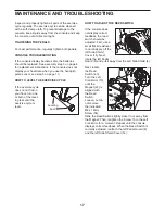
Page 17: ... one or both of the level ing feet until the exercise cycle is level HOW TO ADJUST THE REED SWITCH If the console does not display correct feedback the reed switch should be adjusted First use a small flat screwdriver to carefully pry off the left Side Shield Cover 14 Next rotate the left Pedal Guard 8 and pull it away from the Left Side Shield 4 Next locate the Reed Switch 49 Turn the Left Crank ...

Page 18: ...exercise must be aerobic Aerobic exercise is activity that requires large amounts of oxygen for prolonged periods of time This increases the demand on the heart to pump blood to the muscles and on the lungs to oxygenate the blood For aerobic exercise adjust the intensity of your exercise until your heart rate is near the highest number in your training zone WORKOUT GUIDELINES Each workout should i...

Page 19: ...illes Stretch With one leg in front of the other reach forward and place your hands against a wall Keep your back leg straight and your back foot flat on the floor Bend your front leg lean forward and move your hips toward the wall Hold for 15 counts then relax Repeat 3 times for each leg To cause further stretching of the achilles tendons bend your back leg as well Stretches Calves achilles tendo...

Page 20: ...20 NOTES ...

Page 21: ...21 NOTES ...

Page 22: ...r 39 1 Flywheel 40 1 Left Pedal 41 1 Resistance Motor 42 2 Stabilizer Endcap 43 2 M8 Nylon Jamnut 44 1 Clamp 45 2 5 16 x 1 Flange Screw 46 4 M6 x 30mm Button Screw 47 2 M4 x 19mm Screw 48 3 M10 x 50mm Button Screw 49 1 Reed Switch Wire 50 1 Lower Wire Harness 51 1 Upper Wire Harness 52 4 M6 x 16mm Screw 53 4 M6 Nylon Locknut 54 29 M4 x 16mm Screw 55 3 M10 Split Washer 56 4 M10 x 85mm Button Screw ...

Page 23: ... 8 14 16 37 2 23 52 38 21 53 60 54 54 54 47 55 48 55 48 56 54 54 45 26 54 54 56 32 21 43 59 44 54 57 58 58 54 45 26 54 25 25 27 28 55 50 51 49 17 43 22 24 30 33 35 35 36 63 46 54 54 54 54 54 54 52 54 54 54 62 62 61 61 54 64 65 23 EXPLODED DRAWING Model No NTEX3196 0 R0408A ...

Page 24: ...al trip charge This warranty does not extend to any product or damage to a product caused by or attrib utable to freight damage abuse misuse improper or abnormal usage or repairs not provided by an ICON authorized service center products used for commercial or rental purposes or products used as store display models No other warranty beyond that specifically set forth above is authorized by ICON I...

Reviews: