background image

29

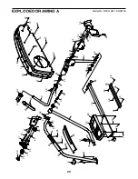
 EXPLODED DRAWING A

4

91

6

8

10

12

16

18

20

22

24

26

27

78

100

29

31

33

33

34

34

35

35

49

38

28

60

61

90

61

61

61

68

68

61

62

67

94

79

62

64

64

56

14

36

78

78

78

74

67

74

67

67

67

67

67

67

67

67

67

73

67

67

67

67

73

67

67

39

61

64

37

37

59

75

80

80

85

60

79

96

96

99

76

98

98

98

98

95

98

98

Model No. NTEL19911.0 R0212A

Summary of Contents for A.C.T. Commercial Plus

Page 1: ...space above for reference QUESTIONS If you have questions or if parts are damaged or missing DO NOT CONTACT THE STORE please contact Customer Care IMPORTANT Please register this product see the limit...

Page 2: ...location shown Note The decal s may not be shown at actual size NORDICTRACK is a registered trademark of ICON IP Inc WARNING DECAL PLACEMENT 2 IMPORTANT PRECAUTIONS 3 BEFORE YOU BEGIN 4 PART IDENTIFI...

Page 3: ...on each side To protect the floor or carpet from dam age place a mat under the elliptical 7 Inspect and properly tighten all parts regu larly Replace any worn parts immediately 8 Keep children under...

Page 4: ...ee the front cover of this manual To help us assist you note the product model number and serial number before contacting us The model number and the location of the serial number decal are shown on t...

Page 5: ...end of this manual The number following the key number is the quantity needed for assembly Note If a part is not in the hardware kit check to see if it has been preassembled Extra parts may be includ...

Page 6: ...g Bracket Screw Assembly requires two persons Place all parts in a cleared area and remove the packing materials Do not dispose of the packing materials until you complete all assembly steps To identi...

Page 7: ...to the Frame 1 3 Identify the Right Upright Cover 21 which is marked with an R sticker and orient it as shown While a second person holds the Right Upright Cover 21 near the Upright 2 tie the indicate...

Page 8: ...d of the Right Handrail 5 into the opening between the Right Outer Shield 17 and the Right Inner Shield 19 Tip Avoid pinching the Right Heart Rate Wire 92 Attach the Right Handrail 5 to the Upright 2...

Page 9: ...2 Attach the Right Handlebar Leg with an M10 x 20mm Screw 61 and an M10 Washer 64 Attach the Left Handlebar Leg 12 in the same way 7 Identify the Right Pedal Arm 15 the Right Pedal 9 and the Right Ped...

Page 10: ...Avoid damaging the Pedal Axle Cover when tightening the Screw Attach the Right Pedal Arm not shown in the same way 9 Apply a small amount of grease to the axle on the Left Pedal Arm Bracket 43 Attach...

Page 11: ...to the Right Outer Shield 17 Attach the Left Large and Small Rail Covers 90 6 in the same way 93 90 16 17 7 6 11 Identify the Right Handlebar 11 which is marked with an R sticker Orient the Right Hand...

Page 12: ...le 3 to the Upright 2 with four M4 x 16mm Screws 67 3 81 67 2 92 Avoid pinching the wires 13 13 Plug the Power Adapter 84 into the receptacle on the front of the elliptical To plug the Power Adapter i...

Page 13: ...arefully move the elliptical to the desired location and then lower it to the floor HOW TO LEVEL THE ELLIPTICAL If the elliptical rocks slightly on your floor during use turn one or both of the leveli...

Page 14: ...in either direction It is recommended that you turn the pedals in the direction shown by the arrow however for variety you can turn the pedals in the opposite direction To dismount the elliptical wait...

Page 15: ...ive workout The console also features an iFit Live mode that enables the console to communicate with your wireless network through an optional iFit Live module With the iFit Live mode you can download...

Page 16: ...u turn on the console You can also press the Manual button to select the manual mode 3 Change the resistance of the pedals as desired As you pedal change the resistance of the pedals by pressing the R...

Page 17: ...n to exit the manual mode or a workout and return to the default menu see HOW TO CHANGE CONSOLE SETTINGS on page 21 to set the default menu If necessary press the Home button again When a wireless iFi...

Page 18: ...on on the console to turn on the console See HOW TO ACTIVATE THE CONSOLE on page 16 2 Select an onboard workout To select an onboard workout press the Calorie Workouts button the Intensity Workouts bu...

Page 19: ...e target rpm Make sure to pedal at a speed that is comfortable for you If the resistance level for the current segment is too high or too low you can manually override the setting by pressing the Resi...

Page 20: ...ext workout in your schedule Press the My Trainer button the My Maps button the World Tour button or the Event Training button to download the next workout of that type in your schedule Press the Comp...

Page 21: ...crease and decrease buttons to adjust the contrast level The following settings can be viewed and changed when an iFit Live module is connected Press the decrease button next to the Enter button to vi...

Page 22: ...using the Volume increase and decrease buttons on the console or the volume control on your MP3 player or CD player THE OPTIONAL CHEST HEART RATE MONITOR Whether your goal is to burn fat or to streng...

Page 23: ...equipment does cause harmful interference to radio or television reception which can be determined by turning the equipment off and on try to correct the interference by one or more of the following m...

Page 24: ...rail covers Then remove all of the screws from the left outer and inner shields there are two sizes of screws in the left outer and inner shields note which size of screw you remove from each hole Th...

Page 25: ...c Exercise If your goal is to strengthen your cardiovascular system you must perform aerobic exercise which is activity that requires large amounts of oxygen for prolonged periods of time For aerobic...

Page 26: ...lles Stretch With one leg in front of the other reach forward and place your hands against a wall Keep your back leg straight and your back foot flat on the floor Bend your front leg lean forward and...

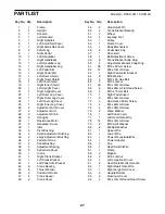
Page 27: ...al Arm Roller 47 2 Crank Spacer 48 2 Crank Cover 49 2 Adjustment Pin 50 4 Crank Bracket Bearing 51 2 Wheel 52 4 Leveling Foot 53 1 Pulley 54 1 Frame Cover 55 1 Eddy Mechanism 56 2 Pedal Axle Cap 57 1...

Page 28: ...Idler Bolt 104 1 Receiver Wire 105 1 M6 Washer 106 1 Flywheel Axle Assembly Tool Grease Packet User s Manual Key No Qty Description Key No Qty Description Note Specifications are subject to change wit...

Page 29: ...100 29 31 33 33 34 34 35 35 49 38 28 60 61 90 61 61 61 68 68 61 62 67 94 79 62 64 64 56 14 36 78 78 78 74 67 74 67 67 67 67 67 67 67 67 67 73 67 67 67 67 73 67 67 39 61 64 37 37 59 75 80 80 85 60 79...

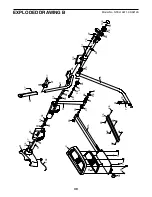
Page 30: ...B 8 11 13 21 23 25 26 27 28 78 29 31 33 33 34 34 35 35 37 59 39 56 49 38 60 61 68 61 61 79 64 64 64 61 67 67 67 67 67 67 67 9 15 36 78 78 78 75 74 74 37 60 79 104 100 98 98 98 98 95 70 98 98 Model No...

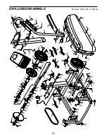
Page 31: ...45 45 46 47 46 47 48 48 50 50 50 50 51 51 52 52 52 52 53 54 55 59 59 61 61 62 69 69 62 62 62 89 96 96 89 65 66 65 66 67 73 67 67 67 73 67 67 67 67 71 71 59 59 57 98 80 80 80 81 82 83 84 61 79 61 79 67...

Page 32: ...not extend to freight damage to the product This warranty will automatically be voided if the product is used as a store display model if the product is purchased or transported outside the USA if al...

Reviews: