nord NORDAC SK 1000E-101-340-A Hardware Description Download Page 23


NORDAC SK 1000E Hardware description 

BU1100 GB 


23


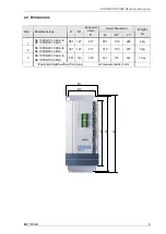
3.3.2  Brake resistor (Optional) 

 
During dynamic braking of the motor, electrical energy is returned to the servo controller. To prevent 
over-voltage  cut-off  ,  the  integrated  brake  chopper,  can  convert  the  recovered  energy  into  heat  by 
connecting an external brake resistor (optional). The capacity of the brake resistor must be matched to 
the  relevant  application.  The  customer  can  select  from  a  wide  range  of  capacities.  Generally,  the 
following  assignments  apply  to  most  application  cases,  sizes  are  calculated  from  the  mass  being 
braked and the cycle times: 
 

Braking resistor 

Length 

Width 

Depth   Connection 

Servo controller 
type SK 1000E- 

Type 

SK BR1- 

Resistor  

Ohm 

Continuous 

consumption 

Pulse 

power 

KW 


mm² 

101-340-A 

201-340-A 

301-340-A 

200/100 

200/300 

100/400 

200 

200 

100 

100 

300 

400 

1.8 

3.0 

3.6 

281 

401-340-A 

501-340-A 

60/600 

60/600 

60 

60 

600 

600 

6.0 

6.0 

331 

121 

48 

0.75 

200 long 

All dimensions in mm, pulse power is dependent on application, max. switch on duration 5% / 120 s


3.3.3  Cable set 

General: 

Drag-resistant and oil-resistant with Cu shield braid 
Cable and plugs UL/CSA authorised  
Kink protection and strain relief 
Working temperature up to 65 degrees Celsius 
DESINA colours: Power cable orange, 

   resolver and encoder cables green, 
   Bus cables: CAN, RS485, RS232 and connection cables violet 

Cable marking: 

UL, CSA 
Protected label 30 mm from each end (plug or shield end): 

Getriebebau NORD 


Part No: e.g. XXXXXXXXX (different for each length) 


Type, e.g. resolver cable 


Length, e.g. 10m 

Cable lengths: 

Ready to use cables 3m, 10m, 15m and 20m from the factory 
Ready to use cables can be ordered in any length. 
 

Orientation of all Sub-D plug housings: 

On the servo controller (view from front, when mounted in control cabinet):  
Cables must hang down with angled hoods 
Longer side (i.e. PIN 1) is always left and shorter side is always right!  
 

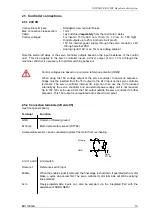
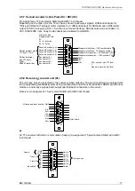
3.3.4   CAN connecting terminal screw connection 

Terminal screw connectors are recommended for connection to the CAN Open socket: 

1.  Bus connector, CAN bus, Sangel, Order No.: 101-690-0BA11 
2.  Erbic CAN bus node, horizontal, with programming connection, ERNI, article No.: 103662 
3.  T-adapter for CAN bus, PEAK-System Technik, No.: IPEK- 003003, 

with PCAN cable without terminating resistor, PEAK-System Technik, No.: IPEK- 003000 

4.  Bus connector, CAN, without connection socket, Helmholz, Order No.: 700-690-0BA11 

Summary of Contents for NORDAC SK 1000E-101-340-A

Page 1: ...BU 1100 GB Status 22 März 2006 Hardware description NORDAC SK 1000E Servo controller SK 1000E 101 340 A SK 1000E 102 340 A T Nr 0604 1192 Getriebebau NORD GmbH Co KG ...

Page 2: ...ied with 4 Erection The erection and cooling of the equipment must be implemented as per the regulations in the corresponding documentation The drive power converter must be protected against unpermitted loads During transport and handling in particular components must not be deformed and or insulation distances must not be changed Touching of electronic components and contacts must be avoided Dri...

Page 3: ...ecting the cables The servo controllers are only intended for permanent connection and may not be operated without effective earthing connections that comply with local regulations regardi ng large leak currents 3 5 mA VDE 0160 requires the installation of a second earthing conductor or an earthing conductor cross section of at least 10 mm 2 Normal FI circuit breakers are generally not suitable as...

Page 4: ...nd encoder in Out Pulse Dir SS1 X2 17 2 5 8 Resolver or encoder unit X1 17 2 5 9 Asynchronous motor cable connections 18 2 5 10 CAN connector optional accessories 18 2 6 Display 19 2 7 Rated peak current 19 2 8 Brake 19 2 9 Basic settings 20 2 10 Commissioning 20 3 TECHNICAL DATA 21 3 1 Electrical data 21 3 2 Functions 21 3 3 Accessories 22 3 3 1 Auxiliary line filter class B 22 3 3 2 Brake resist...

Page 5: ... integrated PLC rounds off the function spectrum of this controller The controller is commissioned with the operating software running under Windows 95 95 2000 NT and XP Commissioning is facilitated by the supplied motor controller database osc illoscope and numerous test functions while the assistant means that anyone can commission the controller Some specifications are currently in preparation ...

Page 6: ...ublication NORD applications for this purpose Encoder resolver or absolute value encoder SSI Incremental encoder emulation output CAN field bus up to 1 MBit s RS 232 and RS 485 up to 56000 Bit s CAN Open Protocol DS301V4 01 DS402V1 1 EDS configuration file provided Variable PDO mapping 10 V analog setpoint interface 6 freely programmable inputs 6 freely programmable short circuit proof outputs 1 f...

Page 7: ...ng unit IP 20 with resolver or encoder design 1MbaudCAN and SSI input or 500kbaudCAN and stepper motor input with or without technical functions Standard design Integrated brake chopper Integrated line filter for limit curve A as per EN 55011 Integrated shield angle CAN Bus RS232 RS485 2 Resolver Encoder input output PLC and programmable 6 inputs and 6 outputs 10 V input reference and limit switch...

Page 8: ... within these limits There is a height dependent minimum distance from the servo controller for these objects This distance must be minimum 2 3 the object height Example cable duct height 60 mm high 2 3 60 mm 40 mm distance Additional distances at the sides are not required Mounting can be implemented directly next to each other e g on DIN rails The installation position is normally vertical The h...

Page 9: ...t depth D L2 B2 L3 Weight ca 1 SK 1000E 101 340 A to SK 1000E 301 340 A 281 121 217 267 100 222 4 kg 2 SK 1000E 401 340 A to SK 1000E 501 340 A 331 121 217 310 100 272 5 kg 3 SK 1000E 801 340 A to SK 1000E 102 340 A 381 163 250 367 140 344 10 kg Equipment depth without front plug All measurements in mm L3 L1 B1 B2 L2 ...

Page 10: ... be earthed on one side on t he servo controller 3 The control cables must be kept distant from load cables by using separate cable ducts etc If cables intersect then an angle of 90 should be used where possible 4 Ensure that the contactors in the cabinet are interference protected either by RC circuits in the case of DC contactors or by free wheeling diodes for AC contactors whereby the interfere...

Page 11: ... slit opening on the bottom enclosure grid The following must be noted 1 Ensure that the power source provides the correct voltage and is set up for the required current see the chapter on technical data Ensure that suitable circuit breakers with the specified current range are switched between the voltage source and the servo controller 2 Connect the line voltage directly to the line terminals L1...

Page 12: ...ernal diameter of the power cable can be max 10 5 mm otherwise the supplied shield and strain relief clamps cannot be fastened For size 3 The connections terminals are suitable for a maximum cable cross section of 4mm When using certain wire sleeves the maximum cable cross section can be reduced to 2 5mm The total external diameter of the power cable can be max 15 5mm otherwise the supplied shield...

Page 13: ...vo controller to power its outputs a bridge must be inserted from the 15V output to the 24V input on the servo controller terminals The servo controller internal I O logic can then use the 15V produced internally by the servo controller and an external power supply unit is not required Up to 150 mA can be used from the 15V output outside the servo controller for other purposes This 15V output is u...

Page 14: ...n the servo controller s own I O circuits Com Differential input for 10V analog control voltage Com 6 Out Freely programmable outputs standard functions such as Position OK Enable etc can be activated via the PLC with the assistance of the NORD SERV 2 5 4 Front panels The figure below shows the front panels connections are clearly marked on the front panels The front panel designs shown differ onl...

Page 15: ...s see accessories Operation of several servo controllers via the RS485 bus requires that the same baud rate is used by all of the units and a different address is set on each unit The terminating resistor integrated in the servo controller must also be connected to the end of t he bus This is explained in the following Can bus section RS232 and RS485 pin assignment 9 pole SUB D female with UMC inc...

Page 16: ...de address OFF OFF OFF OFF 0 1 OFF OFF OFF ON 1 2 OFF OFF ON OFF 2 3 OFF OFF ON ON 3 4 OFF ON OFF OFF 4 5 OFF ON OFF ON 5 6 OFF ON ON OFF 6 7 OFF ON ON ON 7 8 ON OFF OFF OFF 8 9 ON OFF OFF ON 9 10 ON OFF ON OFF 10 11 ON OFF ON ON 11 12 ON ON OFF OFF 12 13 ON ON OFF ON 13 14 ON ON ON OFF 14 15 ON ON ON ON 15 16 Address settings for the bus on the quadruple DIP switch The addresses for CAN nodes are...

Page 17: ...ed with output and feedback connectors on the motor Resolver pin assignment 15 pole male SUB D with UMC inch thread or 5V TTL encoder with Hall or commutation tracks pin assignment 15 pole female SUB D with UMC inch thread 15 8 9 1 Second Encoder In A Second Encoder In A Second Encoder In B Second Encoder In B Encoder out A Encoder out A Encoder out B Encoder out B Stepper motor Pulse SSI encoder ...

Page 18: ...s are identified conforming to standards in the terminal box Polarity can be ignored for the temperature sensor and brake 2 5 10 CAN connector optional accessories Various screw terminal connectors are available for the connection to the CAN Open socket in addition to other additional NORD accessories The customer can cut CAN cables also available from NORD to the length required and connect them ...

Page 19: ...r parameters so that the motor is also thermally protected 2 8 Brake The servo controller has a parameterisable brake control system The application time and ventilating time parameters can be set in NORD SERV parameter dialog Motor A relay is integrated in the servo controller to directly switch the motor brake 24 V must be supplied on the secondary side as the servo controller only has a floatin...

Page 20: ...he encoder used and its limit frequency The encoder used in NORD standard motors 2048 inc rpm has up to 85 C a limit frequency of 200kHz 6000 rpm and up to 100 C just 100kHz 3000 rpm Long incremental encoder connection cables lead to a not insignificant voltage drop due to the ohmic resistance of the encoder supply circuits The encoders used have an operating voltage tolerance of 5 250mV If this i...

Page 21: ... increment number NORD standard 2048 inc rpm 85 C max 200kHz 6000 rpm 100 C max 100 kHz 3000 rpm Protective measures against Over temperature of servo controller and motor Over and under voltage Short circuit earth fault overload Regulation and control Travelling profile torque speed and positioning control all in a control cycle time of 50µs Setpoint input analog 10 V resolution 12Bit Speed calcu...

Page 22: ...e switching External auxiliary filter Filter class B External brake resistor For applications with high generational recovered energy 100W 300W 400W 600W 3 3 1 Auxiliary line filter class B An auxiliary external line filter optional can be looped into the line supply of the servo controller to maintain the increased noise suppression level class B as per EN 55011 When connecting the line filter co...

Page 23: ...ant with Cu shield braid Cable and plugs UL CSA authorised Kink protection and strain relief Working temperature up to 65 degrees Celsius DESINA colours Power cable orange resolver and encoder cables green Bus cables CAN RS485 RS232 and connection cables violet Cable marking UL CSA Protected label 30 mm from each end plug or shield end Getriebebau NORD Part No e g XXXXXXXXX different for each leng...

Page 24: ... confirm compliance with the EMC directive Precise details are therefore given below about the EMC behaviour of this product based on the proviso that it is installed according to the guidelines and instructions described in this documentation Class 1 General for industrial environments Complies with the EMC standard for power drives EN 61800 3 for use in secondary environments industrial and when...

Page 25: ...be applied to the shield angle and to comply with Class 3 also on the entry to the control cabinet EMC screw connection Overview of standards that as per EN 61800 3 product standard for FU are based on EN 50081 510082 and must be complied with Standard Limit value class Interference emission Cable based interferences EN55011 A B with filter Radiated interference EN55011 A B with filter Interferenc...

Page 26: ... in the control cabinet these must also be cleaned or replaced regularly The equipment must be sent to the following address if it needs repairing Enercon NORD Electronic GmbH Finkenburgweg 11 26603 Aurich Germany For queries about repairs please contact Getriebebau NORD GmbH Co Telephone 49 4532 401 514 or 401 518 Fax 49 4532 401 555 If a servo controller is sent in for repair no liability can be...

Page 27: ...r 2 6 70794 Filderstadt Sielmingen Tel 49 7158 956 08 0 Fax 49 7158 956 08 20 Sales office Nürnberg Getriebebau NORD GmbH Co KG Schillerstr 3 90547 Stein Tel 49 911 672 311 Fax 49 911 672 471 Sales office München Getriebebau NORD GmbH Co KG Untere Bahnhofstr 38a 82110 Germering Tel 49 89 840 794 0 Fax 49 89 840 794 20 East branch Getriebebau NORD GmbH Co KG Leipzigerstr 58 09113 Chemnitz Tel 49 37...

Page 28: ...sia Jln Raya Serpong KM 7 Kompleks Rumah Multi Guna Blok D No 1 Pakulonan Serpong Tangerang West Java Indonesia Tel 62 21 531 222 22 Fax 62 21 531 222 88 info nord hg com Italy Italien NORD Motoriduttori s r l Via Modena 14 I 40019 Sant Agata Bolognese BO Tel 39 51 682 9711 Fax 39 51 957 990 info nord it com Netherlands Niederlande NORD Aandrijvingen Nederland B V Voltstraat 12 NL 2181 HA Hillegom...

Reviews: