


SK 500E – Brief instructions for frequency inverters
12
BU 0540 EN-1516
2.1 SK 5xxE, standard version
Normally the frequency inverter is mounted directly on the rear wall of a
control cabinet. For this, two, of for Size 5 to 7 four, suitable wall-mounting
brackets are supplied, which must be pushed into the heat sink on the rear
of the inverter. Above Size 8, the mounting device is already integrated.
Alternatively, for Size 1 to 4 the wall mounting brackets can be inserted at
the side of the cooling element in order to minimise the necessary depth of
the control cabinet.
In general, care must be taken that the rear of the cooling element is
covered with a flat surface and that the device is mounted vertically. This
enables optimum convection, which ensures fault-free operation.
Device type
Si
ze
Housing dimensions
Wall-mounting
A
B
C
D
E 1
∅
SK 5xxE-250- … to SK 5xxE-750- ...
Size 1
186
74
2)
153
220
/
5.5
SK 5xxE-111- … to SK 5xxE-221- …
Size 2
226
74
2)
153
260
/
5.5
SK 5xxE-301- … to SK 5xxE-401- …
Size 3
241
98
181
275
/
5.5
SK 5xxE-551- 340… to SK 5xxE-751- 340…
Size 4
286
98
181
320
/
5.5
SK 5xxE-551- 323… to SK 5xxE-751- 323…
Size 5
327
162
224
357
93
5.5
SK 5xxE-112- 340… to SK 5xxE-152- 340…
Size 5
327
162
224
357
93
5.5
SK 5xxE-112- 323…
Size 6
367
180
234
397
110
5.5
SK 5xxE-182- 340… to SK 5xxE-222- 340…
Size 6
367
180
234
397
110
5.5
SK 5xxE-152- 323… to SK 5xxE-182- 323…
Size 7
456
210
236
485
130
5.5
SK 5xxE-302- 340… to SK 5xxE-372- 340…
Size 7
456
210
236
485
130
5.5
SK 5xxE-452- 340… to SK 5xxE-552- 340…
Size 8
598
265
286
582
210
8.0
SK 5xxE-752- 340… to SK 5xxE-902- 340…
Size 9
636
265
286
620
210
8.0
SK 5xxE-113- 340… to SK 5xxE-133- 340…
Size
10
720
395
292
704
360
8.0
SK 5xxE-163- 340…
Size
11
799
395
292
783
360
8.0
400 V (…-340…) and 500 V (…-350…) - FI:
identical dimensions and weights
All dimensions in [mm]
1)
2)
Size 10 and 11: The stated value corresponds to the distance between the outer fasteners. A third fastening hole is
provided in the middle
For the use of bottom-mounted brake resistors = 88 mm
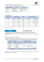
A=
Total length
1)
B=
Total width
1)
C=
Total height
1)
D=
Longitudinal hole
spacing
2)
E=
Lateral hole spacing
2)
1) Delivery condition
2) Fixing dimensions
B
A
C
D
D A
B
E
C


