WWW.NORAC.CA
PRECISION
DEFINED
Page
14
Visit
www.solutions.norac.ca
for
more
system
installation
and
troubleshooting
info.
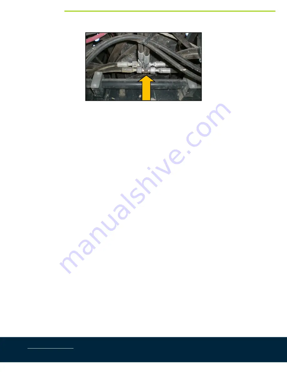
Figure
8:
Case
Main
Lift
Tee
Location
12.
Disconnect
the
raise
hose
that
runs
from
the
Case
valve
block
to
the
main
lift
tee
and
install
the
6FORX
‐
6MORT
fitting
(*F03).
Reconnect
the
raise
hose
to
the
tee.
13.
Connect
the
NORAC
hose
(H05)
that
is
connected
to
the
“B”
port
on
the
3
rd
station
of
the
NORAC
block
to
the
tee
fitting
(*F03).
14.
Disconnect
the
lower
hose
that
runs
from
the
Case
valve
block
to
the
main
lift
tee
and
install
the
6FORX
‐
6MORT
fitting
(*F03).
Reconnect
the
lower
hose
to
the
tee.
15.
Connect
the
NORAC
hose
(H05)
that
is
connected
to
the
“A”
port
on
the
3
rd
station
of
the
NORAC
block
to
the
tee
fitting
(*F03).
16.
Install
four
(4)
6MOR
‐
6FORX90
fittings
(F14)
onto
the
6FORXR
‐
6MORT
tees
(F13).
17.
Connect
hose
H06
between
the
F14
fittings
on
the
lower
(“A”)
lines.
18.
Connect
hose
H06
to
the
F14
fitting
on
the
left
raise
(“B”)
line.
19.
Connect
hose
H07
to
the
F14
fitting
on
the
right
raise
(“B”)
line.
20.
Install
four
(4)
6MB
‐
6MOR
fittings
(F12)
onto
the
ports
on
the
wing
roll
cylinder
(H20).
21.
Install
four
(4)
6MOR
‐
6FORX90
fittings
(F14)
onto
the
F12
fitting
on
the
wing
roll
cylinder
(H20).
22.
Connect
hose
H07
from
the
right
raise
line
to
the
outer
port
on
the
cable
end
of
the
wing
roll
cylinder
(H20).
23.
Connect
hose
H06
from
the
left
raise
line
to
the
outer
port
on
the
opposite
end
of
the
wing
roll
cylinder
(H20).
24.
Connect
hose
H06
between
the
“A”
port
on
the
wing
roll
cylinder
(H20)
and
the
“A”
port
on
the
NORAC
expansion
block.


